Oil container and dispenser

Active Publication Date: 2005-01-13
EMERSON ELECTRIC CO
View PDF10 Cites 2 Cited by
  • Summary
  • Abstract
  • Description
  • Claims
  • Application Information

AI Technical Summary

Benefits of technology

[0004] In accordance with the present invention, an oiler is provided by which the foregoing and other problems and disadvantages of oilers heretofore available are minimized or overcome. Further in this respect, and in accordance with one aspect of the invention, an oiler bucket structure is provided by which frictional interengagement between the bucket and an underlying surface is reduced relative to that encountered with a flat bottom bucket. This advantageously reduces the force and physical effort required to pull the oiler along an underlying surface. In accordance with another aspect of the invention, an oiler bucket is contoured to reduce the minimum amount of oil required in the bucket for continual operation relative to the amount of oil required in connection with the use of oilers heretofore available. This further enhances pulling of the oiler by reducing the weight thereof, and the latter makes it easier to lift and carry the oiler. In accordance with yet another aspect of the invention, the hose bulkhead fitting and bucket of an oiler are structured and structurally interrelated so as to minimize or eliminate side forces and bending of the hose at the fitting in response to an o

Problems solved by technology

While oilers of the foregoing character serve their intended purpose, there are a number of disadvantages attendant to the structure and use thereof.
In this respect, for example, the number of parts and the necessary assembly operations with respect thereto make the cost and the weight thereof undesirably high.
Moreover, during use, the pump hose is often used to pull the bucket and pan assembly from one location to another along the underlying floor or other support surface, and the frictional engagement between the surface and the flat bottom of the bucket makes the sliding movement difficult.
Further in this respect, the flat bottom bucket contour requires maintaining an excessive quantity of oil in the bucket for continuous operation of the oiler, and the weight of the oil adds to the difficulty with respect to sliding t

Method used


Image

  • Oil container and dispenser
  • Oil container and dispenser
  • Oil container and dispenser

Examples


Embodiment Construction

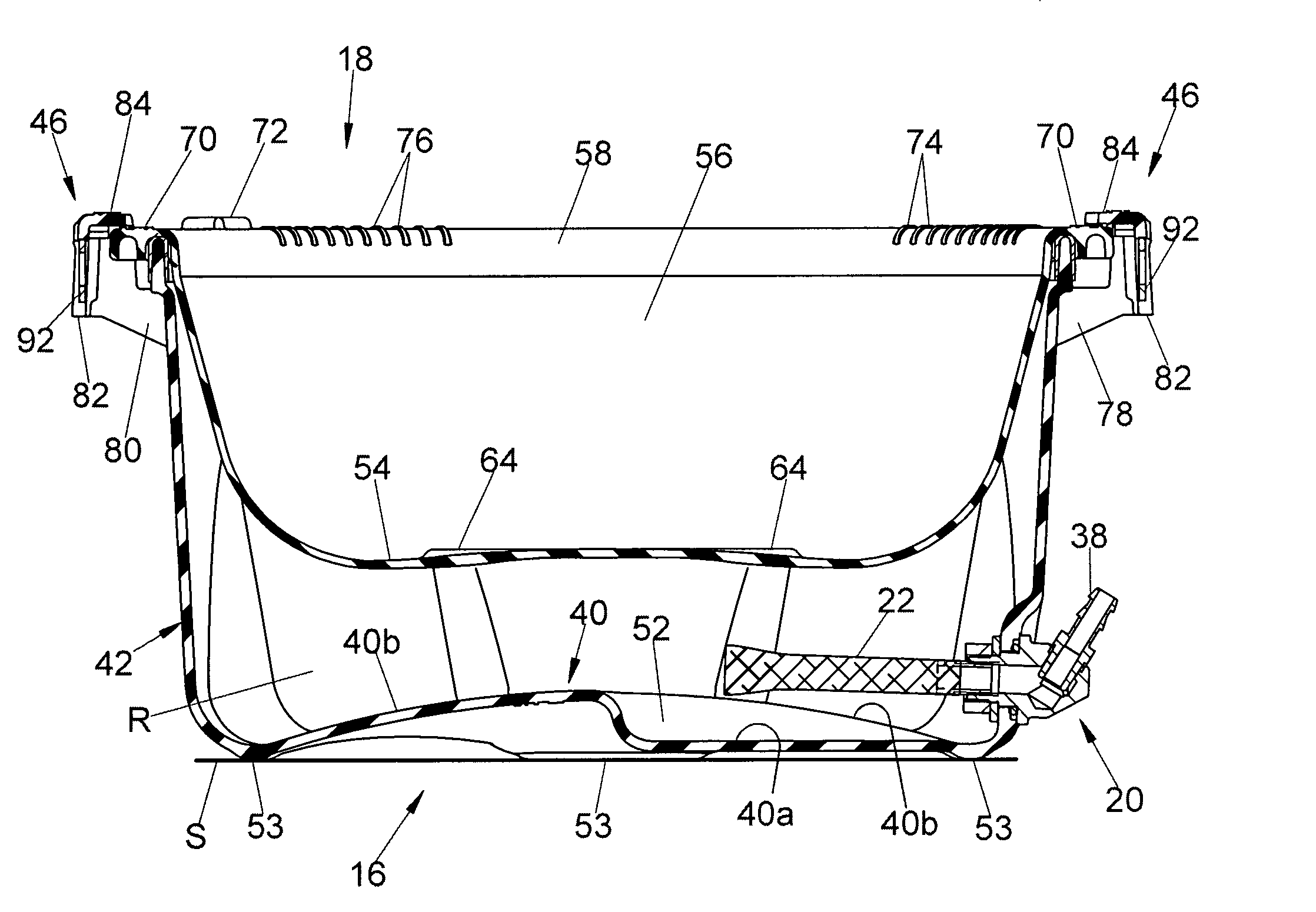
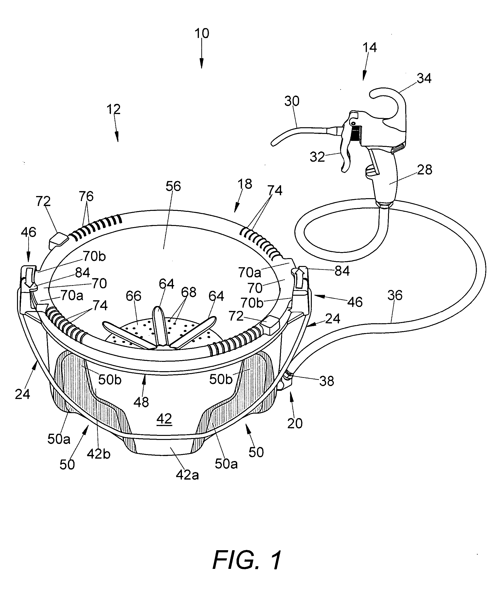
[0028] Referring now in greater detail to the drawings, wherein the showings are for the purpose of illustrating a preferred embodiment of the invention only, and not for the purpose of limiting the invention, a portable oiler 10 is illustrated in FIG. 1 which comprises a container 12 in accordance with the present invention and a manually operable pump 14 for dispensing oil in the container onto a workpiece supported in a metal working machine such as a pipe or rod threader. In use, as is well known, container 12 is positioned beneath the working area of the machine so as to receive oil and metal chips which drop from the working area.

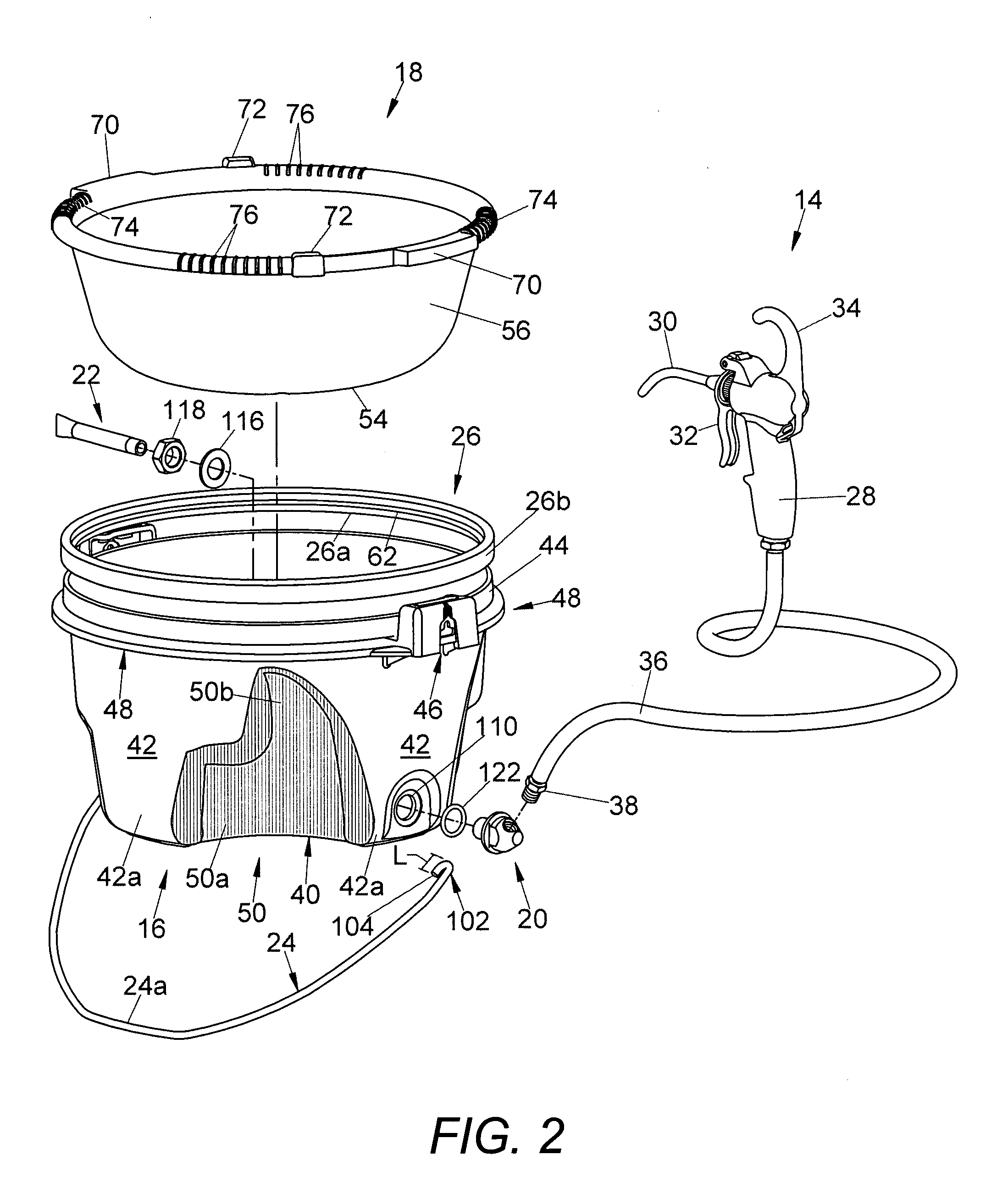
[0029] As best seen in FIG. 2, the primary component parts of a container in accordance with the invention are a bucket 16 which, as will become apparent hereinafter, provides a reservoir for oil to be pumped from the container to the working area, and a drip pan or tray 18 for receiving metal chips and oil dripping from the working area and retainin...


PUM


Abstract

A container for a manually operable oil dispenser for use with metal working machines comprises a bucket providing a reservoir for oil to be dispensed and a pan in the bucket for catching oil and chips dropping thereinto and for returning the oil to the bucket. The bucket has a bottom, a sidewall and an annular upper end, and the pan has an apertured bottom spaced above the bottom of the bucket, a sidewall inwardly of the sidewall of the bucket and an upper end overlying and slidable circumferentially relative to the upper end of the bucket. The bucket and pan have locking members interengaging during relative sliding displacement therebetween to releasably interengage the bucket and pan against separation. The bottom and sidewall of the bucket are contoured to minimize the volume of oil necessary in the reservoir area for continual operation of the dispenser, and the bucket is provided with a bulkhead fitting for attachment to a dispensing pump hose at an angle of 45° to horizontal.

Description

BACKGROUND OF THE INVENTION [0001] This invention relates to the art of containers for fluid dispensers and, more particularly, to a container for oil to be dispensed onto a workpiece in metal working machinery such as pipe threaders. [0002] Portable oil dispensers have been provided heretofore for use with pipe threading apparatus, for example. One such oil dispenser has been available from the Ridge Tool Company of Elyria, Ohio under the latter's product designation No. 418 Oiler, comprising a bucket providing a reservoir for thread cutting oil, a drip pan removably mounted on the bucket for receiving chips and oil from the thread cutting apparatus and separating the oil for return to the reservoir area in the bucket, and a handheld trigger operated pump connected to the bucket by a flexible hose and operable by a threading machine operator to dispense oil onto a workpiece being threaded. The initial version of the 418 Oiler, and others currently on the market which are similar th...

Claims


Application Information

Patent Timeline
IPC IPC(8): F16N31/00
CPCF16N31/004
Inventor IWAMASA, JONATHAN M.MORRIS, STEVEN K.
Owner EMERSON ELECTRIC CO
Why Eureka
Try Eureka