Low voltage luminaire assembly

a low-voltage, luminaire technology, applied in the direction of contact members penetrating/cutting insulation/cable strands, coupling device connections, lighting support devices, etc., can solve the problems of time-consuming and laborious installation of known under-cabinet lights, and achieve simple, reliable, and economical manufacturing and use.

Inactive Publication Date: 2005-01-13
HUBBELL INC
View PDF67 Cites 82 Cited by
  • Summary
  • Abstract
  • Description
  • Claims
  • Application Information

AI Technical Summary

Benefits of technology

[0006] The present invention provides a low-voltage, under-cabinet lighting fixture or luminaire assembly for permanent or temporary and surface or recessed mounting. In general, the luminaire assembly is low-profile and modular with quick-release electrical connections to connect individual lamp assemblies and a transformer to objects quickly and easily. Further, the component parts of the modular luminaire assembly are simple, reliable, and economical to manufacture and use.

Problems solved by technology

Conventional under-cabinet lights suffer from various drawbacks.
Since the raceways must be measured and cut to fit specific surfaces, installation of known under-cabinet lights can be time-consuming.
Also, if a raceway is measured incorrectly, additional time and materials are wasted.
Furthermore, if an electrical wire is pierced incorrectly when installing individual lamp assemblies on the raceway, the entire under-cabinet light may have to be replaced.
Moreover, failure of a transformer supplied with some under-cabinet lights to convert 120 volts to 12 volts usually requires replacement of the entire under-cabinet light.

Method used


Image

  • Low voltage luminaire assembly
  • Low voltage luminaire assembly
  • Low voltage luminaire assembly

Examples


first embodiment

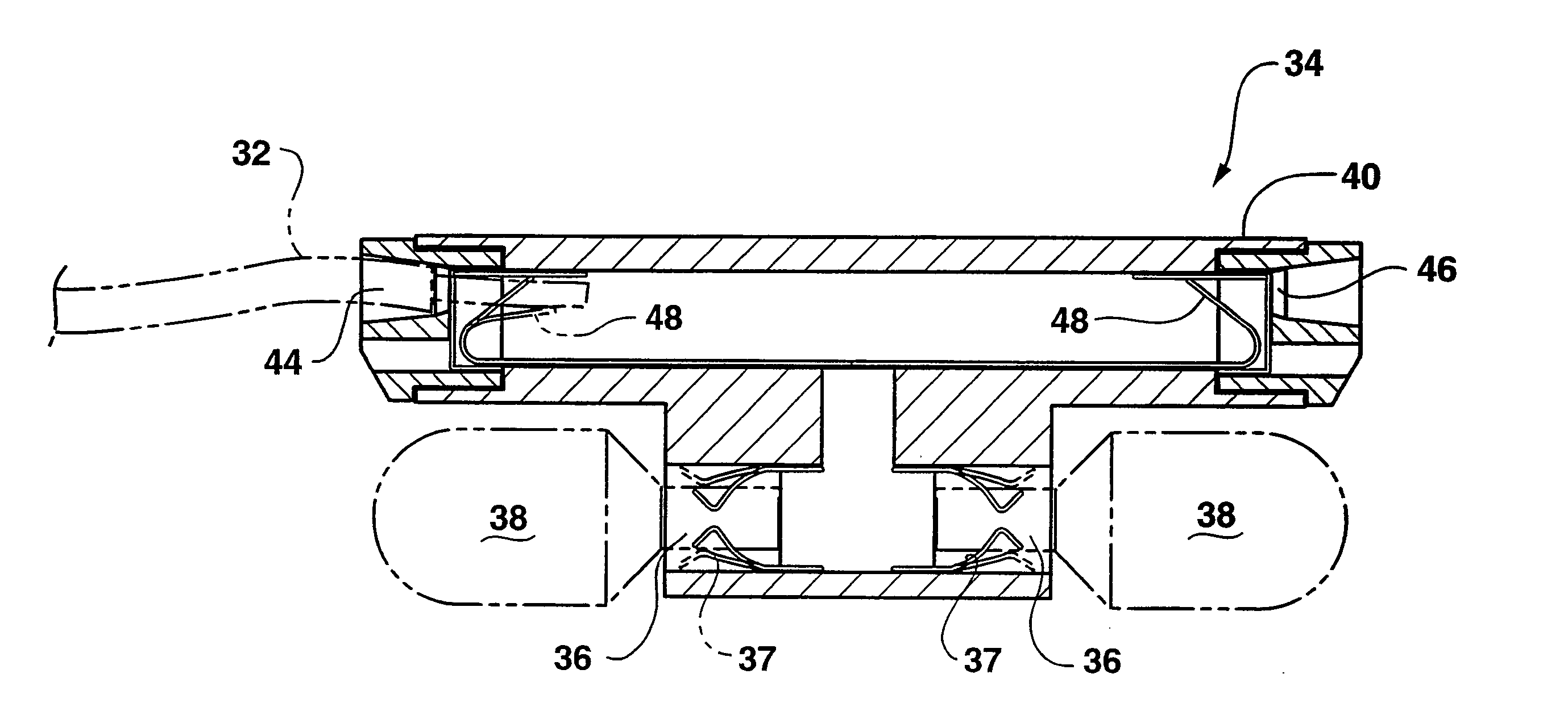
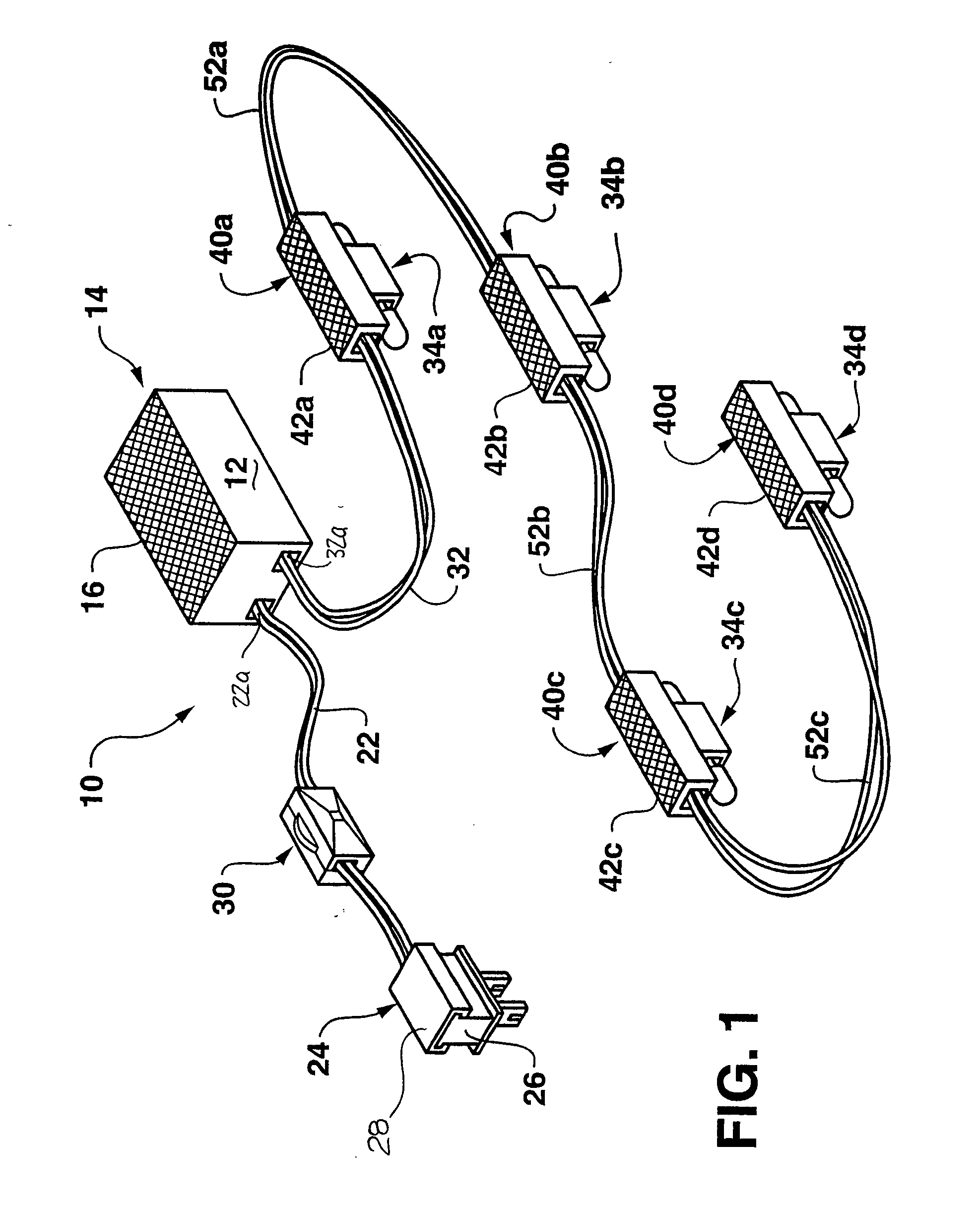
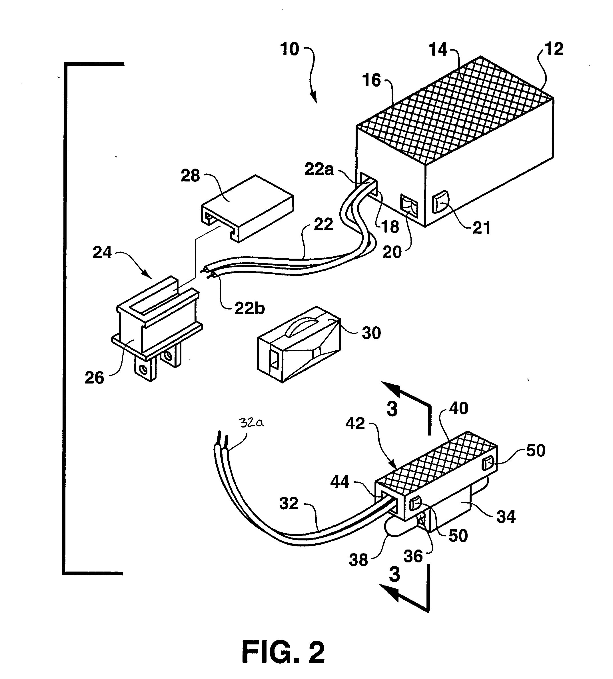
[0020] An under-cabinet lighting fixture or luminaire assembly 10, according to the present invention, is shown in FIG. 1. The luminaire assembly 10 has a transformer 12, an electrical plug component 24, a rotary dimmer switch 30, and a plurality of lamp holders 34a-d. The transformer 12 has a mounting side 14 that is attachable to a surface area (not shown). A double-sided adhesive tape 16 may be used to mount the transformer 12, but the transformer may be mounted in any suitable manner. Similarly, the plurality of lamp holders 34a-d have respective mounting sides 40a-d attachable by double-sided adhesive tape 42a-d. In this example, a wax-type paper (not shown) is peeled away from the mounting sides 14 and 40a-d to expose the respective adhesive tapes 16 and 42a-d for adherence to the surface area. However, any attachment mechanism may be substituted for the double-sided adhesive tape 16, 42a-d, such as other forms of adhesive, screws, bolts, nails, nuts, rivets, pins, snap-fittin...

second embodiment

[0033] A lamp holder assembly 134 according to the present invention includes a lamp holder 134a and a mounting assembly 140 for attaching the lamp holder assembly 134 to a surface area, as shown in FIG. 4. In this embodiment, the mounting assembly 140 defines a securement part 142 having an arcuate opening 156 therein that receives a screw, bolt, nail, rivet, pin and the like to secure the lamp holder assembly 134 to the surface area. A guide piece 154 is also provided to flush-mount the lamp holder assembly 134 in a surface area corner or along an edge of a wall. It is to be noted that various other shapes and orientations of the foregoing elements may be provided and such variations and modifications are within the scope of the invention. Also, similar securement parts and guide pieces may be provided to mount the transformer 12.

[0034] The invention may be better understood with reference to the following embodiments of operations and methods of using the present invention.

[0035...


PUM


Abstract

A low-voltage luminaire assembly is provided with a transformer and a lamp holder, one or more of which have quick-release connections. Methods for installing and servicing the luminaire assembly are also provided. The luminaire assembly may also have a plurality of lamp holders, a plurality of input and output electrical wires, a rotary dimmer switch, and an electrical plug component. The transformer and lamp holders are mounted to an object and the electrical wires are tailored to the necessary installation dimensions, thereby providing a luminaire assembly that is easily and neatly installable to any object in any desired configuration.

Description

FIELD OF THE INVENTION [0001] The present invention relates to a low voltage luminaire assembly. More particularly, the present invention relates to a low-voltage luminaire assembly having a quick-release transformer and at least one quick-release lamp holders that are mountable to a surface. Still more particularly, the present invention relates to a method of installing, removing and replacing components of a low voltage luminaire assembly. BACKGROUND OF THE INVENTION [0002] Light fixtures are used in homes and buildings to provide various forms of illumination. Some light fixtures serve both functional and aesthetic purposes, such as for illumination of work surfaces below cabinets and in cabinetry and furniture in constricted areas. [0003] In one form, strings of low-voltage accent lights are provided as part of an under-cabinet installation kit to be used by builders or by after-market consumers. These under-cabinet lights are typically mounted to surfaces under kitchen cabinet...

Claims


Application Information

Patent Timeline
Patent Type & Authority Applications(United States)
IPC IPC(8): F21S2/00F21S4/00F21V21/08F21V23/04H01R4/48H01R13/66
CPCF21S2/005F21S4/003F21S8/037H01R13/6633F21V23/04H01R4/4836F21V21/08F21S4/20H01R4/48365
Inventor HYDER, LASHANNON S.
Owner HUBBELL INC
Why Eureka
Try Eureka