Method and apparatus for reducing quantization-induced beam errors by selecting quantized coefficients based on predicted beam quality

Active Publication Date: 2005-01-13
THE BOEING CO
View PDF32 Cites 21 Cited by
  • Summary
  • Abstract
  • Description
  • Claims
  • Application Information

AI Technical Summary

Problems solved by technology

In such situations, a spacecraft's on-board navigation system (which relies on inertial sensors and perhaps Sun, Earth, Moon, star, and magnetic sensors as well) often cannot support the precise pointing requirement.
However, the accuracy of the digital beacon system is negatively affected by the performance limitations of the digital beam-forming technique and its implementation.
Although some digital beacon sensor errors can be am

Method used


Image

  • Method and apparatus for reducing quantization-induced beam errors by selecting quantized coefficients based on predicted beam quality
  • Method and apparatus for reducing quantization-induced beam errors by selecting quantized coefficients based on predicted beam quality
  • Method and apparatus for reducing quantization-induced beam errors by selecting quantized coefficients based on predicted beam quality

Examples


first embodiment

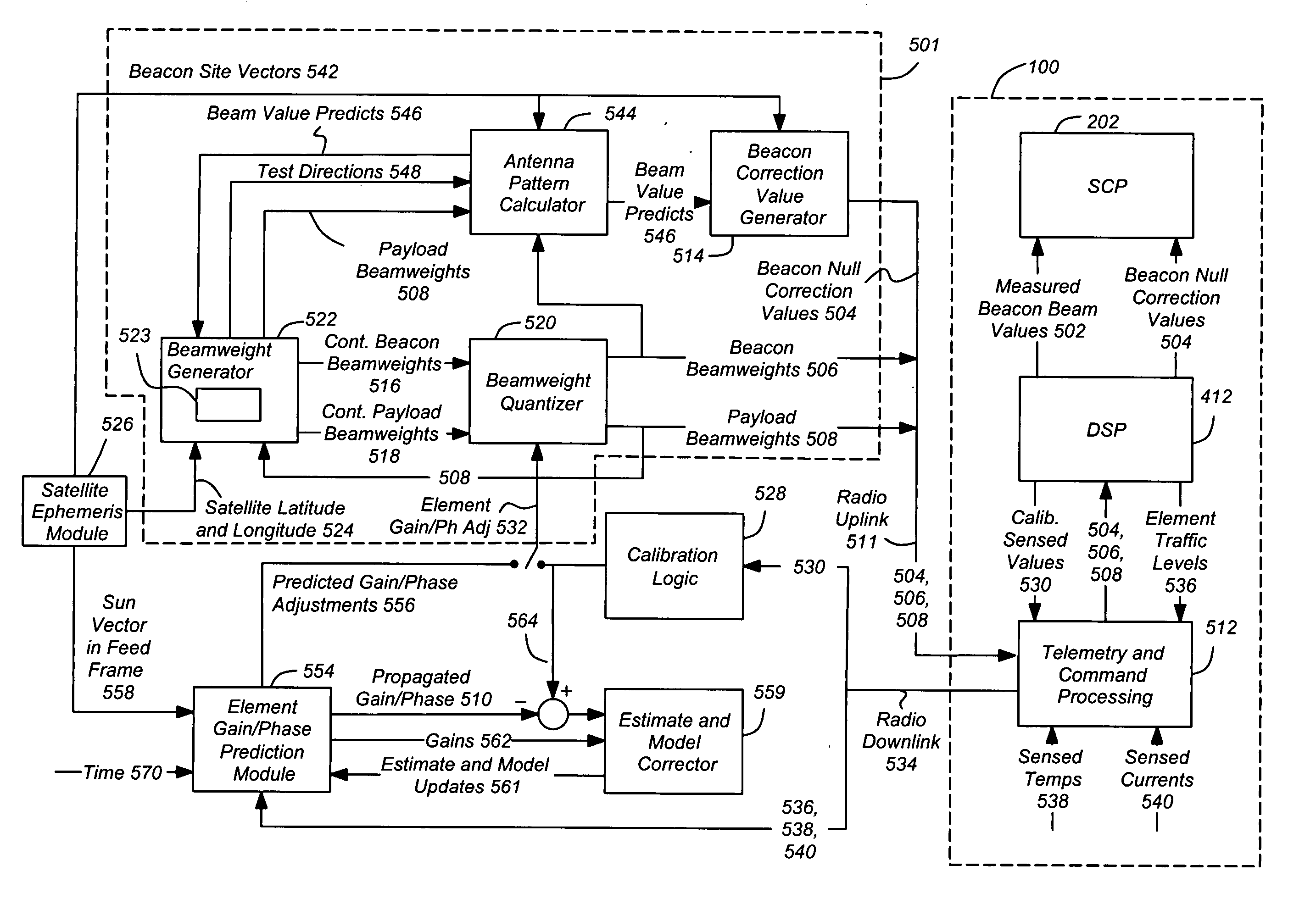
[0082]FIG. 8A is a diagram presenting an illustration of the In block 802, a desired beacon beam value is computed. This can be accomplished as described above with respect to FIGS. 6A and 6B. In block 804, a predicted measured beacon beam value is computed. These beacon beam values are used to generate a beacon beam correction, as shown in block 806.

second embodiment

[0083]FIG. 8B is a diagram presenting an illustration of the In block 852, a desired beacon angle value is computed. This can be accomplished as described above with respect to FIGS. 6A and 6B (e.g. the computation of the desired beacon azimuth and elevation angles). A predicted measured beacon beam value is computed, as shown in block 804. In this embodiment these predicted measured beacon beam values are used to compute a predicted measured beacon angle value, as shown in block 854. This can be accomplished using the same beacon site vectors 542 and a functional copy of the onboard beacon value processing software (e.g. in the SCP 202) to calculate the desired measured beacon azimuth and elevation angles for those beacon site vectors 542. The computed desired beacon angle value and the computed predicted measured beacon angle value are then used to generate a beacon angle correction, as shown in block 856. In one embodiment, the correction values are the difference between the pr...


PUM


Abstract

A method and apparatus for correcting a beam error is disclosed. One embodiment of the method comprises the steps of selecting beamweight coefficients based on the satellite orbital data, evaluating an effect of quantization of the beamweight coefficients on the beam error, and selecting beamweight coefficients based at least in part upon the evaluation of the effect of beamweight coefficient quantization on beam error. One embodiment of the apparatus comprises a beamweight correction module for selecting beamweight coefficients based on satellite orbital data, for evaluating the effect of quantization of the beamweight coefficients on beam error, and for selecting beamweight coefficients based at least in part upon the evaluation of the effect of beamweight coefficient quantization on beam error. The beamweight correction module comprises a beamweight generator and a beamweight quantizer for quantizing beamweights from the beamweight generator.

Description

CROSS-REFERENCE TO RELATED APPLICATIONS [0001] This application claims benefit of U.S. Provisional Patent Application No. 60 / 486,625, entitled “MITIGATION OF BEAM-FORMING ERRORS DUE TO GAIN / PHASE SHIFTS AND QUANTIZATION,” by Richard A. Fowell and Hanching G. Wang, filed Jul. 11, 2003, which application is hereby incorporated by reference herein. [0002] This application is also related to the following co-pending and commonly assigned patent application(s), all of which applications are incorporated by reference herein: [0003] application Ser. No. 10 / 319,273, entitled “DIGITAL BEACON ASYMMETRY AND QUANTIZATION COMPENSATION,” filed on Dec. 30, 2002, by Hanching G. Wang and Chih-Chien Hsu, attorney's docket number PD-200109; [0004] application Ser. No. ______, “entitled METHOD AND APPARATUS FOR CORRECTION OF QUANTIZATION-INDUCED BEACON BEAM ERRORS,” filed on same date herewith, by Richard A. Fowell and Hanching G. Wang, attorney's docket number PD-02-1123; and [0005] application Ser. N...

Claims


Application Information

Patent Timeline
IPC IPC(8): H01Q3/00H01Q3/26H04B7/185H04B7/204
CPCH04B7/2041H01Q3/267
Inventor FOWELL, RICHARD A.WANG, HANCHING G.
Owner THE BOEING CO
Why Eureka
Try Eureka