Correction system and method of analog front end

Inactive Publication Date: 2005-01-13
NOVATEK MICROELECTRONICS CORP
View PDF4 Cites 112 Cited by
  • Summary
  • Abstract
  • Description
  • Claims
  • Application Information

AI Technical Summary

Benefits of technology

[0020] We can further get the essence and advantage of this

Problems solved by technology

Owing to the error of the devices, the image sensor 14 often outputs signals higher than zero.
This problem makes error of the following signals outputted by the sensitive region.
In fact, the black pixel signal is even higher than 100 mV due to the inevitable noise such as device error.
It is a fundamental error of the devi

Method used


Image

  • Correction system and method of analog front end
  • Correction system and method of analog front end
  • Correction system and method of analog front end

Examples


Embodiment Construction

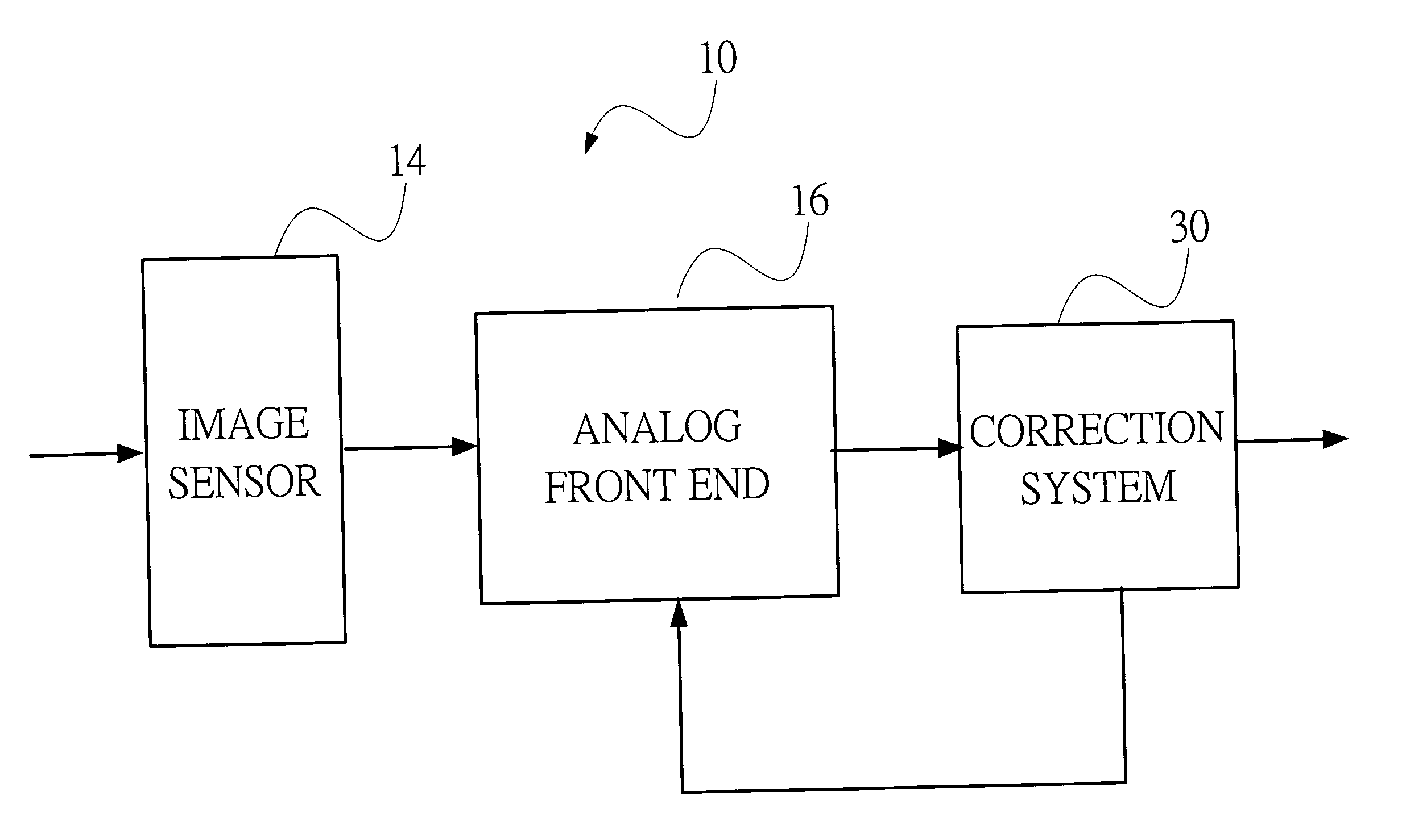
[0029] Please refer to FIG. 4. FIG. 4 is a schematic diagram of an image sensor 14 and an AFE 16 with a correction system 30 according to the present invention. The present invention relates to a correction system 30 applied in an analog front end 16. The analog front end 16 is used to receive a plurality of pixel signals outputted by an image sensor 14 in a proper sequence and convert the plurality of pixel signals to a corresponding plurality of digital output signals after amplifying the plurality of pixel signals with a gain factor. In the preferred embodiment of this invention, the image sensor 14 is a charge couple device (CCD). In another embodiment, the analog front end 16 is used to amplify and convert a plurality of analog output signals, which is received from a signal source in proper sequence, to a corresponding plurality of digital output signals. The plurality of analog output signals include a plurality of basis signals and a plurality of content signals. Each basis ...


PUM


Abstract

The present invention is a correction system applying in an analog front end(AFE). The correction system comprises a correction module, a first digital to analog converter(DAC1) and a second digital to analog converter(DAC2). The correction is used to generate a gain error correction and black pixel signal error correction when the black pixel signal is inputted into the AFE. The correction module corrects the digital output signals generated by the AFE according to the gain error correction. The correction module input the black pixel signal error correction to the DAC1 to generate a first analog correction signal to correct the signal inputted into the AFE. The present invention effectively corrects the signal error generated by the AFE to make the AFE output the corrected digital output signal.

Description

FIELD OF THE INVENTION [0001] The present invention relates to a correction system and method of an analog front end, and more particularly, to a correction system and method of an analog front end applied in an image capture device. BACKGROUND OF THE INVENTION [0002] Analog Front End (AFE) is an important device in an image-capturing device, for example, a digital camera, a digital video camera, etc. It is used to receive the pixel signals from the image sensor and convert the pixel signals to the digital signals for following process. [0003] The analog pixel signals outputted by the image sensor should be processed with the signal modulation and the analog-to-digital conversion to be the digital output signals for following process. Please refer to FIG. 1, FIG. 1 is a schematic diagram of the conventional image capture device 10. The image capture device 10 captures the optical image by an optical system 12 and processes the signals by the following devices as an image sensor 14, ...

Claims


Application Information

Patent Timeline
IPC IPC(8): H04N5/228H04N5/367H04N5/378H04N9/04
CPCH04N5/3575H04N5/378H04N5/361H04N25/616H04N25/63H04N25/75
Inventor CHOU, KUO-YU
Owner NOVATEK MICROELECTRONICS CORP
Why Eureka
Try Eureka