Device and method for wavefront measurement of an optical imaging system by means of phase-shifting interferometry

Inactive Publication Date: 2005-01-13
CARL ZEISS SMT GMBH
View PDF5 Cites 45 Cited by
  • Summary
  • Abstract
  • Description
  • Claims
  • Application Information

AI Technical Summary

Benefits of technology

The disturbing influence in a non-parallel direction can be adequately suppressed, for example in a refinement of the invention, by carrying out the inventive method with the aid of the inventive device. As mentioned above, the mask-displacing or phase-shifting grating structure, limited to one-dimension, of the device renders a fast phase-shifting movement in a n

Problems solved by technology

Particularly for this type of system with motionally rigid coupling of the phase-shifting structure and detector element, however, when use is made of the method, conventional for this purpose of evaluating the wavefront interoferograms, it is observed that there is a limitation of the accuracy which can be achieved for th

Method used


Image

  • Device and method for wavefront measurement of an optical imaging system by means of phase-shifting interferometry
  • Device and method for wavefront measurement of an optical imaging system by means of phase-shifting interferometry
  • Device and method for wavefront measurement of an optical imaging system by means of phase-shifting interferometry

Examples


Example

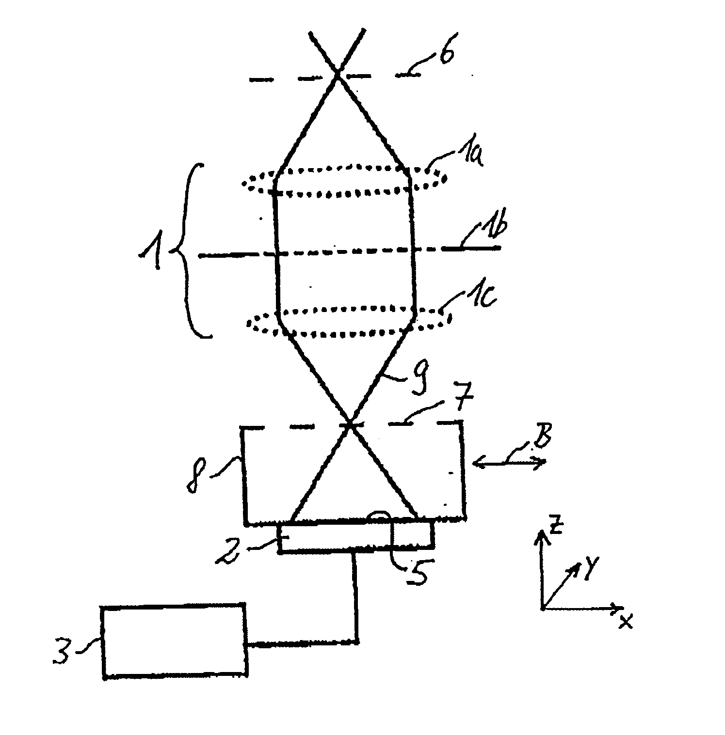
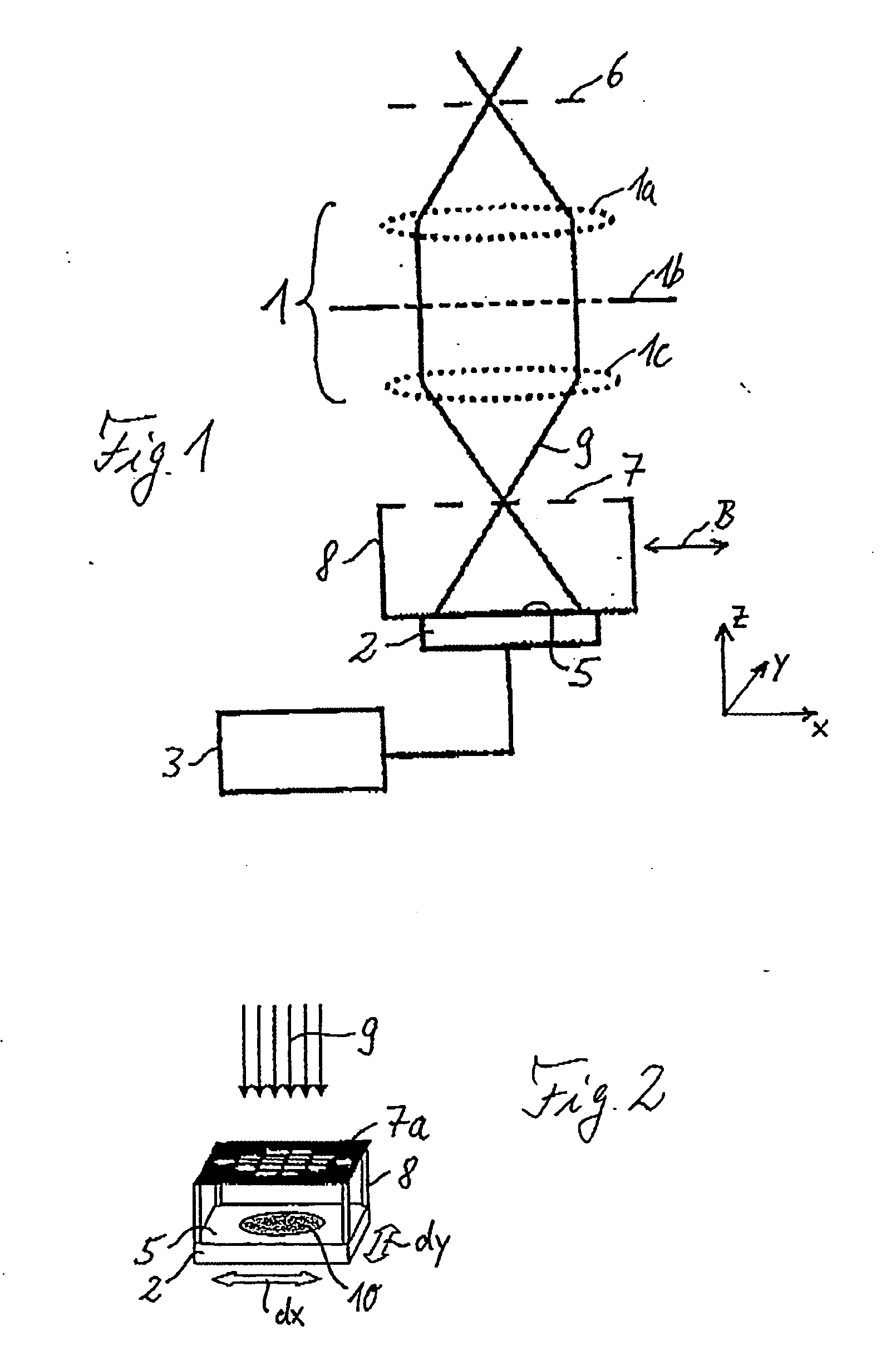
FIG. 1 illustrates a typical design of a device for wavefront measurement by means of shearing interferometry for the purpose of determining image errors and, in particular aberrations, using the example of a projection objective 1 of a microlithography projection exposure machine as optical imaging system to be measured. The objective 1 is represented in a simplified fashion by an object-side lens 1a, an objective pupil 1b and an image-side lens 1c. A coherence mask 6 is arranged on object side, preferably in the object plane of the objective 1. In a fashion corresponding thereto, a phase-shifting diffraction grating 7 is arranged on the image side, preferably in the image plane of the objective 1, such that it can move laterally in the xy-plane orthogonal to the z-direction of the optical axis of the system. The distorted pupil of the objective 1 is imaged onto a detector element 2, more precisely onto a detection plane 5 of the same. Coupled to the detector element 2, which can b...


PUM


Abstract

Device and method for wavefront measurement of an optical imaging system by means of phase-shifting interferometry, having a mask structure (6a) to be arranged on the object side, and/or a grating structure (7a) to be arranged on the image side. The object-side mask structure includes one or more one-dimensional mask structure patterns, and the image-side grating structure includes one or more two-dimensional grating structure patterns. Alternatively, conversely, the mask structure includes one or more two-dimensional patterns, and the grating structure includes one or more one-dimensional patterns. Additionally or alternatively, a pupil position offset caused by a lateral relative movement of the mask structure and detector element can be taken into account by back calculating the interferogram, respectively recorded by the detector element, using an associated phase-shift characteristic, or by a computational correction of wavefront derivatives, obtained from the recorded interferograms, in the direction of lateral movement. The method and/or the device can by used, for example, for determining aberration in the case of high-resolution projection objectives of microlithography exposure machines using shearing or point interferometry.

Description

The following disclosure is based on German Patent Application No. 103 16 123.6 filed on Apr. 4, 2003, which is incorporated into this application by reference. FIELD OF THE INVENTION The invention relates to a device for wavefront measurement of an optical imaging system by means of a phase-shifting interferometry technique, having a mask structure to be arranged on the object side, and a grating structure to be arranged on the image side, and to a method for wavefront measurement of an optical imaging system by means of a phase-shifting interferometry technique, wherein a phase-shifting structure and a detector element are moved laterally relative to the optical imaging system to be measured. BACKGROUND AND OBJECTS OF THE INVENTION Devices and methods of this type serve the purpose, for example, of determining the imaging quality and / or image errors of high-resolution optical imaging systems interferometrically with high precision. An important field of application is the corre...

Claims


Application Information

Patent Timeline
IPC IPC(8): G01B9/02G01J9/04
CPCG01J9/04G03F7/706G01M11/0271G01M11/0264
Inventor HAIDNER, HELMUTEMER, WOLFGANGHOCH, RAINERWEGMANN, ULRICHSCHRIEVER, MARTINGOEPPERT, MARKUS
Owner CARL ZEISS SMT GMBH
Why Eureka
Try Eureka