Processing technique for forward looking sonar

a processing technique and forward-looking sonar technology, applied in the field of forward-looking sonar systems, can solve the problems of often lacking image quality for complex or 3-dimensional beamformed data sets, and achieve the effect of improving image clarity and reducing nois

Active Publication Date: 2005-01-13
FARSOUNDER
View PDF2 Cites 55 Cited by
  • Summary
  • Abstract
  • Description
  • Claims
  • Application Information

AI Technical Summary

Benefits of technology

[0003] The invention defined in this application extracts target information from a set of beamformed data and also provides for the removal of various sources of noise. Targets are intelligently extracted from the beamformed data set through the use of correlation techniques. These correlation techniques can include, but are not limited to spatial, temporal, spectral, and geometrical correlation factors. In many environments, a priori information can be used to improve image clarity. For example, in cases where a solid sea floor is detected or specified by the user or some other input into the system, potential targets detected by the sonar system which are located below the sea floor can be ignored. This is one example of reducing noise composed of spurious targets that are clearly not part of the actual sea environment. This application is not limited to marine environments and may be applied to any environment where 2 or 3-dimensional signal data is used.

Problems solved by technology

Traditional beamformed data can be ambiguous to the interpreter be it a human or another system, due to it's complexity and / or the existence of various sources of noise within the data such as surface noise and sidelobes.
This approach is often lacking in image quality for complicated or 3-dimensional beamformed data sets.

Method used


Image

  • Processing technique for forward looking sonar
  • Processing technique for forward looking sonar
  • Processing technique for forward looking sonar

Examples


Embodiment Construction

[0014] The invention will be described in connection with certain preferred embodiments, with reference to the following illustrative figures so that it may be more fully understood. With reference to the figures, it is stressed that the particulars shown are by way of example and for purposes of illustrative discussion of the preferred embodiments of the present invention only, and are presented in the cause of providing what is believed to be the most useful and readily understood description of the principles and conceptual aspects of the invention. In this regard, no attempt is made to show structural details of the invention in more detail than is necessary for a fundamental understanding of the invention, the description taken with the drawings making apparent to those skilled in the art how the several forms of the invention may be embodied in practice.

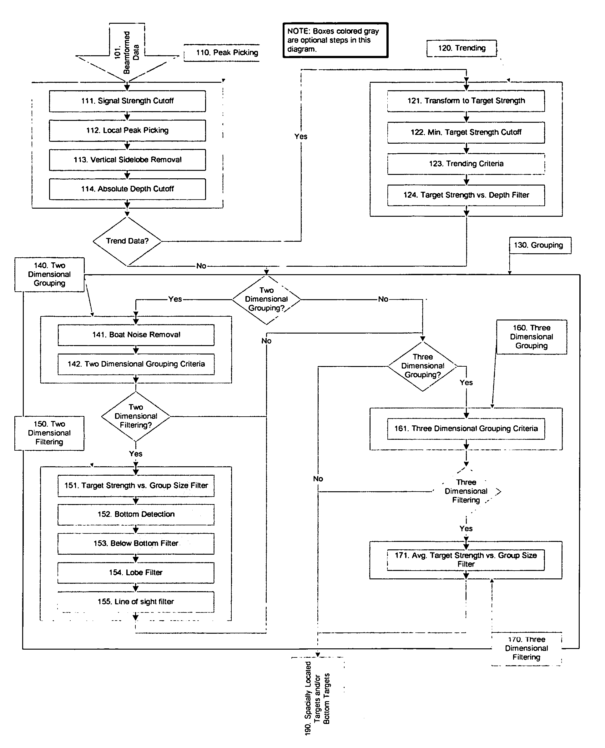
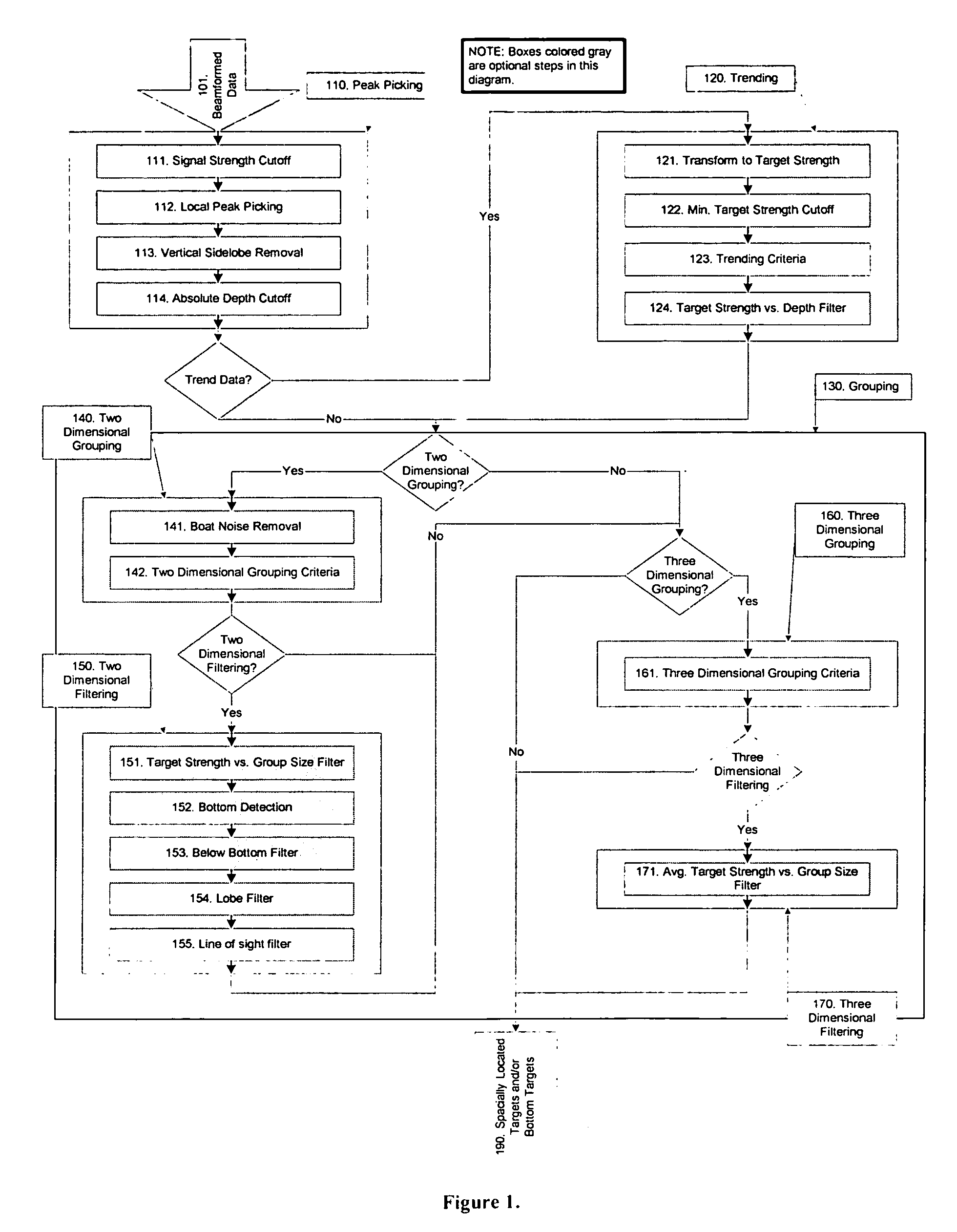
[0015] A block diagram of the preferred embodiment of this system is given in FIG. 100. In the preferred embodiment, the bea...


PUM


Abstract

A processing technique and transducer field of view architecture for use as part of an imaging sonar system to develop three-dimensional images of the space below, to the sides, and forward of a ship.

Description

PRIORITY [0001] Priority is claimed to U.S. patent application Ser. No. 60 / 474402, which was filed on Jun. 2, 2003.BACKGROUND [0002] An essential part of any forward looking sonar system is the ability to successfully utilize the data presented by the system. Typically, beamformed data is used to determine the location of objects within a volume of fluid, hereby defined as targets. Traditional beamformed data can be ambiguous to the interpreter be it a human or another system, due to it's complexity and / or the existence of various sources of noise within the data such as surface noise and sidelobes. Thus, a need exists to extract the essential target information from a set of beamformed data while eliminating sources of noise. Traditional display systems have tried to simplify the display by simply finding and displaying a single point within each beam of the beamformed data set. These systems are often called profiling sonars. Common single point detection routines extract these po...

Claims


Application Information

Patent Timeline
Patent Type & Authority Applications(United States)
IPC IPC(8): G01S7/527G01S15/89
CPCG01S15/89G01S7/5273
Inventor ZIMMERMAN, MATTHEW JASONCOOLIDGE, MATTHEW ALDENLAPISKY, EVAN MIKEL
Owner FARSOUNDER
Why Eureka
Try Eureka