Symbol boundary detection device and method for use in OFDM system

a detection device and symbol technology, applied in multi-frequency code systems, digital transmission, amplitude demodulation, etc., can solve problems such as lack of flexibility, inter-symbol interference (isi), and influence on the efficiency of the receiver

Active Publication Date: 2005-01-13
REALTEK SEMICON CORP
View PDF15 Cites 46 Cited by
  • Summary
  • Abstract
  • Description
  • Claims
  • Application Information

AI Technical Summary

Problems solved by technology

Because the channel impulse response (CIR) is not ideal in practical, a symbol passing through the channel 106 influences the subsequent symbol receiving operation in the receiver, thereby causing inter-symbol interference (ISI).
This fixed method, however, lacks of flexibility, and misjudgment of the reference point will be made when the pre-cursor response is longer or has many relative

Method used


Image

  • Symbol boundary detection device and method for use in OFDM system
  • Symbol boundary detection device and method for use in OFDM system
  • Symbol boundary detection device and method for use in OFDM system

Examples


Embodiment Construction

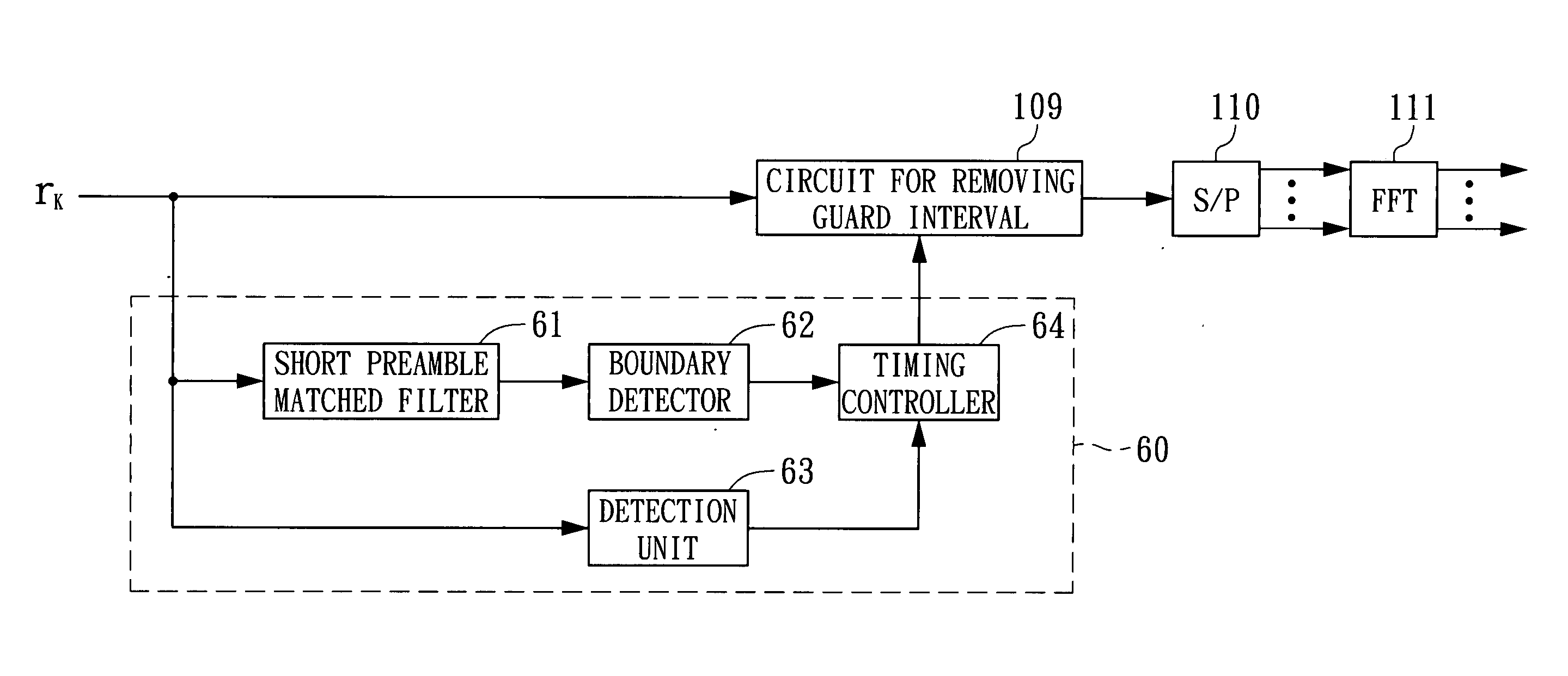
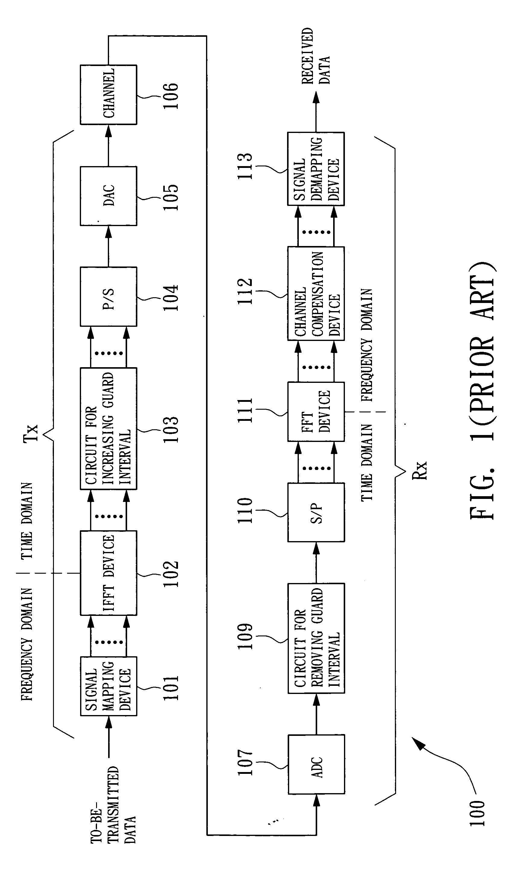
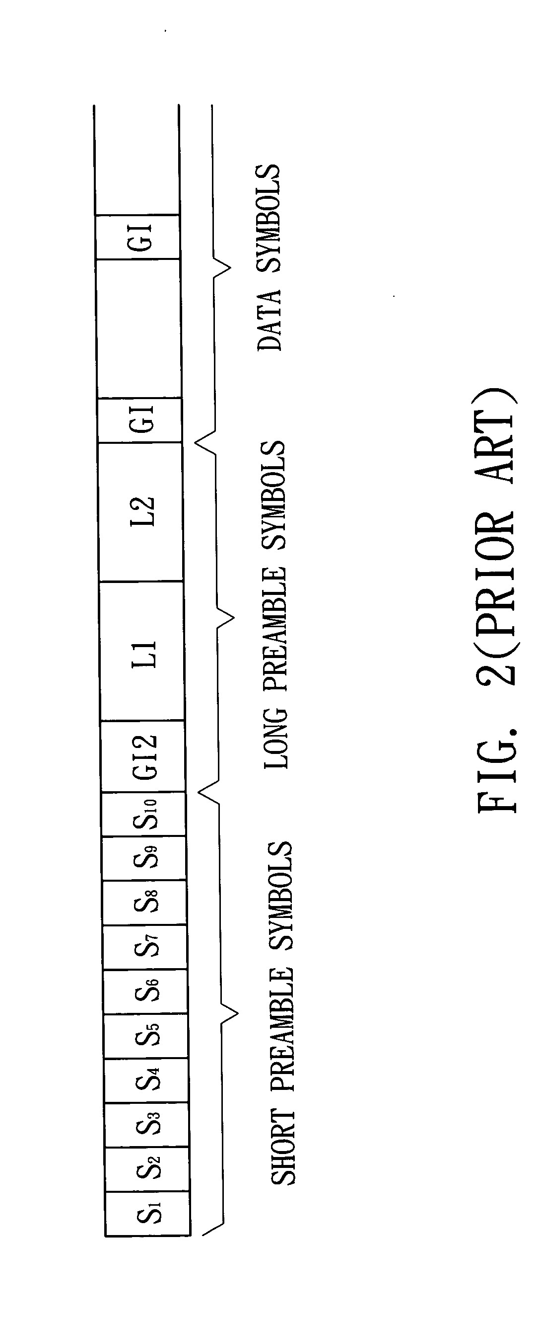
The implementation of this invention will be described with reference to the OFDM system 100 of FIG. 1. As shown in FIG. 2, the received / transmitted code frame of the OFDM system 100 sequentially has a periodical short preamble, a long preamble including a pilot symbol and its guard interval GI2, and a plurality of data symbols and their guard intervals GI. Herein, it is also assumed that the sampling number is N within one period of the short preamble. FIG. 6 is a block diagram showing a symbol boundary detection device 60 proposed in conjunction with this code frame architecture of the embodiment of the invention. Referring to FIG. 6, the boundary detection device 60 includes a short preamble matched filter 61 for receiving a sampling signal rk of the code frame and performs the operation of Equation (1-2). When the short preamble is received, the matched filter 61 outputs an estimated value of the channel impulse response (CIR) of the OFDM system 100.

The boundary detection dev...


PUM


Abstract

A symbol boundary detection device and a method thereof for use in a receiver of a multi-channel communication system. The device utilizes a threshold to make an auxiliary judgement so as to select a proper symbol boundary reference point within an early range. The threshold may be flexibly set in response to different characteristics of the systems. In addition, a pilot symbol guard interval matched filter is further utilized to determine whether a pilot symbol guard interval is received.

Description

This application claims the benefit of Taiwan application Serial No. 092118541, filed on Jul. 8, 2003, the subject matter of which is incorporated herein by reference. BACKGROUND OF THE INVENTION 1. Field of the Invention The invention relates in general to an OFDM (orthogonal frequency division multiplexing) communication system, and more particularly to symbol boundary detection device and method for use in an OFDM system. 2. Description of the Related Art Recently, a multi-carrier (or multi-channel, multi-tone) communication technology has been widely used in data transmission, such as the OFDM (orthogonal frequency division multiplexing) technology for use in the IEEE 802.11a / g WLAN (wireless local area network). FIG. 1 is a block diagram showing a typical OFDM system. The OFDM system 100 respectively puts the to-be-transmitted data into N sub-channels in the frequency domain through a signal mapping device 101 in a transmitter. Then, an inverse fast Fourier transform (IFFT...

Claims


Application Information

Patent Timeline
IPC IPC(8): H04L27/26
CPCH04L27/2605H04L27/2678H04L27/2675H04L27/2662
Inventor LIU, DER-ZHENGTANG, SONG-NIENLIU, TAI-CHENGYEN, KUANG-YU
Owner REALTEK SEMICON CORP
Why Eureka
Try Eureka