Ultrasonic transducer for parametric array

Inactive Publication Date: 2005-01-13
POMPEI FRANK JOSEPH
View PDF25 Cites 17 Cited by
  • Summary
  • Abstract
  • Description
  • Claims
  • Application Information

AI Technical Summary

Benefits of technology

[0012] In the preferred embodiment, the second cover portion includes a protective mesh layer and an ornamental cover layer, such that the protective layer is sandwiched between the second retaining layer and the ornamental layer. Further, the second retaining layer preferably has a thickness sufficient to create a spacing between the vibrator film layer and the protective and ornamental layers that reduces or effectively eliminat

Problems solved by technology

However, this can be problematic because a typical ultrasonic transducer, such as the typical piezoelectric transducer, has a diameter of only about ¼ inch.
Although the ultrasonic transducer might be made larger to achieve higher levels of audible sound, this can also be problematic.
However, as the electrostatic transducer increases in size, the size of the backplate a

Method used


Image

  • Ultrasonic transducer for parametric array
  • Ultrasonic transducer for parametric array
  • Ultrasonic transducer for parametric array

Examples


Embodiment Construction

[0020] U.S. Provisional Patent Application No. 60 / 328,516 filed Oct. 9, 2001 entitled ULTRASONIC TRANSDUCER is incorporated herein by reference.

[0021] A high performance, highly reliable ultrasonic transducer is disclosed that has a reduced cost of manufacture. The presently disclosed ultrasonic transducer has a laminated construction that allows the formation of multiple ultrasonic film transducers using a single layer of ultrasonic vibrator film and a substantially singular mechanical structure.

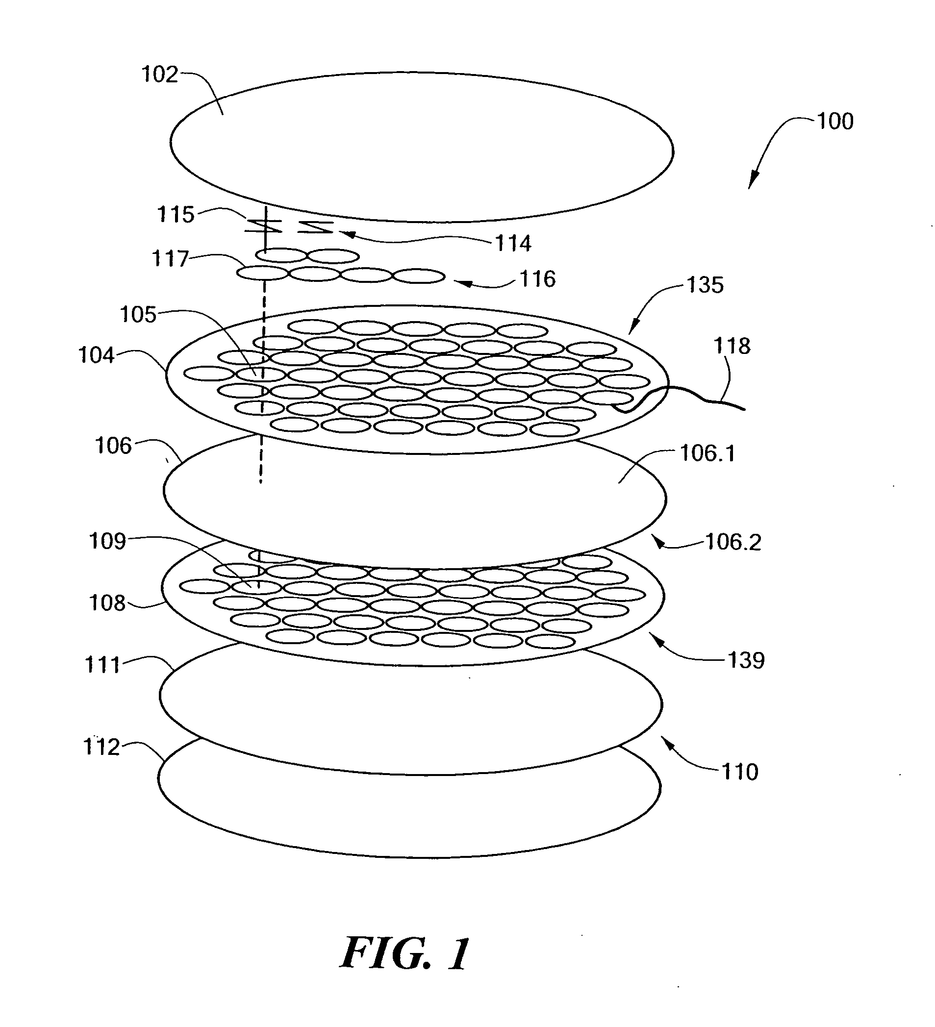
[0022]FIG. 1 depicts an illustrative embodiment of an ultrasonic transducer 100, in accordance with the present invention. In the illustrated embodiment, the ultrasonic transducer 100 comprises a first cover portion 102, a first insulative retaining layer 104, a vibrator film layer 106, a second insulative retaining layer 108, and a second cover portion 110. As shown in FIG. 1, the vibrator film layer 106 is sandwiched between the first and second retaining layers 104 and 108. Further, th...


PUM


Abstract

An ultrasonic transducer having a reduced cost of manufacture. The ultrasonic transducer includes a first insulative retaining layer, a second insulative retaining layer, and a vibrator film layer sandwiched between the first and second retaining layers. The first retaining layer includes a first plurality of apertures formed therethrough, and the second retaining layer includes a second plurality of apertures formed therethrough, in which the second apertures are substantially in registration with the first apertures. The ultrasonic transducer further includes a first cover portion having a plurality of spring/backplate assemblies connected thereto, and a second cover portion. The combination of the first retaining layer, the vibrator film layer, and the second retaining layer is sandwiched between the first and second cover portions of the ultrasonic transducer. The laminated construction of the ultrasonic transducer allows the formation of an array of ultrasonic film transducers using a single piece of ultrasonic vibrator film.

Description

CROSS REFERENCE TO RELATED APPLICATIONS [0001] This application claims priority of U.S. Provisional Patent Application No. 60 / 328,516 filed Oct. 9, 2001 entitled ULTRASONIC TRANSDUCER.STATEMENT REGARDING FEDERALLY SPONSORED RESEARCH OR DEVELOPMENT [0002] N / A BACKGROUND OF THE INVENTION [0003] The present invention relates generally to acoustic transducers, and more specifically to a high performance ultrasonic transducer having a reduced cost of manufacture. [0004] Ultrasonic transducers are known that may be employed in parametric speaker systems for generating sonic or ultrasonic signals in nonlinear transmission media. For example, an array of ultrasonic transducers may be employed in a parametric speaker system for generating sonic (i.e., audio) signals in air or water. A conventional parametric audio system typically includes a modulator configured to modulate an ultrasonic carrier signal with at least one audio signal, at least one driver amplifier configured to amplify the mo...

Claims


Application Information

Patent Timeline
IPC IPC(8): B06B1/02G01S7/521H04R19/00
CPCB82Y10/00B82Y30/00H04R19/02H04R31/00B06B1/0292B06B1/0622
Inventor POMPEI, FRANK
Owner POMPEI FRANK JOSEPH
Why Eureka
Try Eureka