Position and orientation detection method and apparatus

a technology apparatus, applied in the field of position and orientation detection technique, can solve the problems of inability to track, inability to obtain position and orientation, and dramatic change in the position of indicators, and achieve the effect of simplified configuration and high accuracy detection results

Inactive Publication Date: 2005-01-13
CANON KK
View PDF14 Cites 73 Cited by
  • Summary
  • Abstract
  • Description
  • Claims
  • Application Information

AI Technical Summary

Benefits of technology

The present invention is conceived in consideration of the above-described conventional art, and has as its obj...

Problems solved by technology

Method 3 is a method that detects the position and orientation of the camera solely by image processing, and thus suffers from an inability to track in cases that the position of the indicators change dramatically from one frame to the next, due, for example, to rapid movement of the head.
Method 1, as has been made problematic already in method 2, using only a 6-DOF sensor gives rise to the problem that the accuracy of the position and orientation obtained is inadequate.
That such a separate apparatus is required means that the detection range of the sensor is restricted to a limited range.
In addition, there is the problem that, depending on the installation site, it might be difficult to install the separate apparatus itself, or, if installation is possible, it might be inconvenient.
Further, there is the problem that the sensor itself remains generally expensive.
However, insofar as the method uses a 6-DOF sensor, the problems of detection range, installation and cost remain unresolved.
However, once any one of the indicators can no longer be observed from the camera, method 3 is totally unable to obtain the position and orientation of the camera.
In other words, a very large number of indicators must be disposed in real space, or the positions of the indicators in three dimensions must be input by some method, and therein lies the problem.
Further, when detecting the indicators from the image, in some instances there might be a problem with the detectional stability of the indicators.
However, such a large indicator cannot always be installed in real space.
As a result, situations arise in which, instead of using a large indicator, for exam...

Method used


Image

  • Position and orientation detection method and apparatus
  • Position and orientation detection method and apparatus
  • Position and orientation detection method and apparatus

Examples


first embodiment

(First Embodiment)

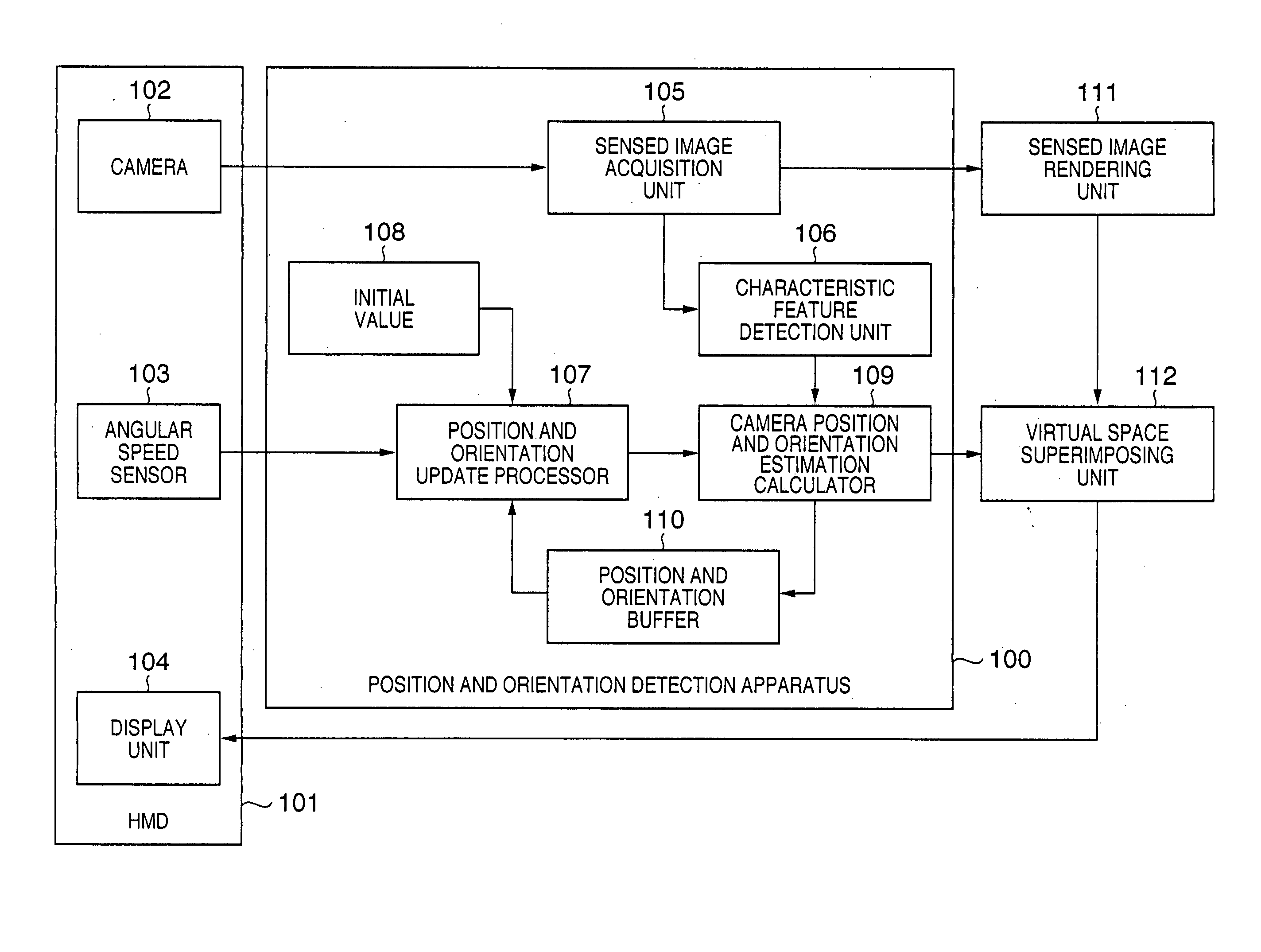
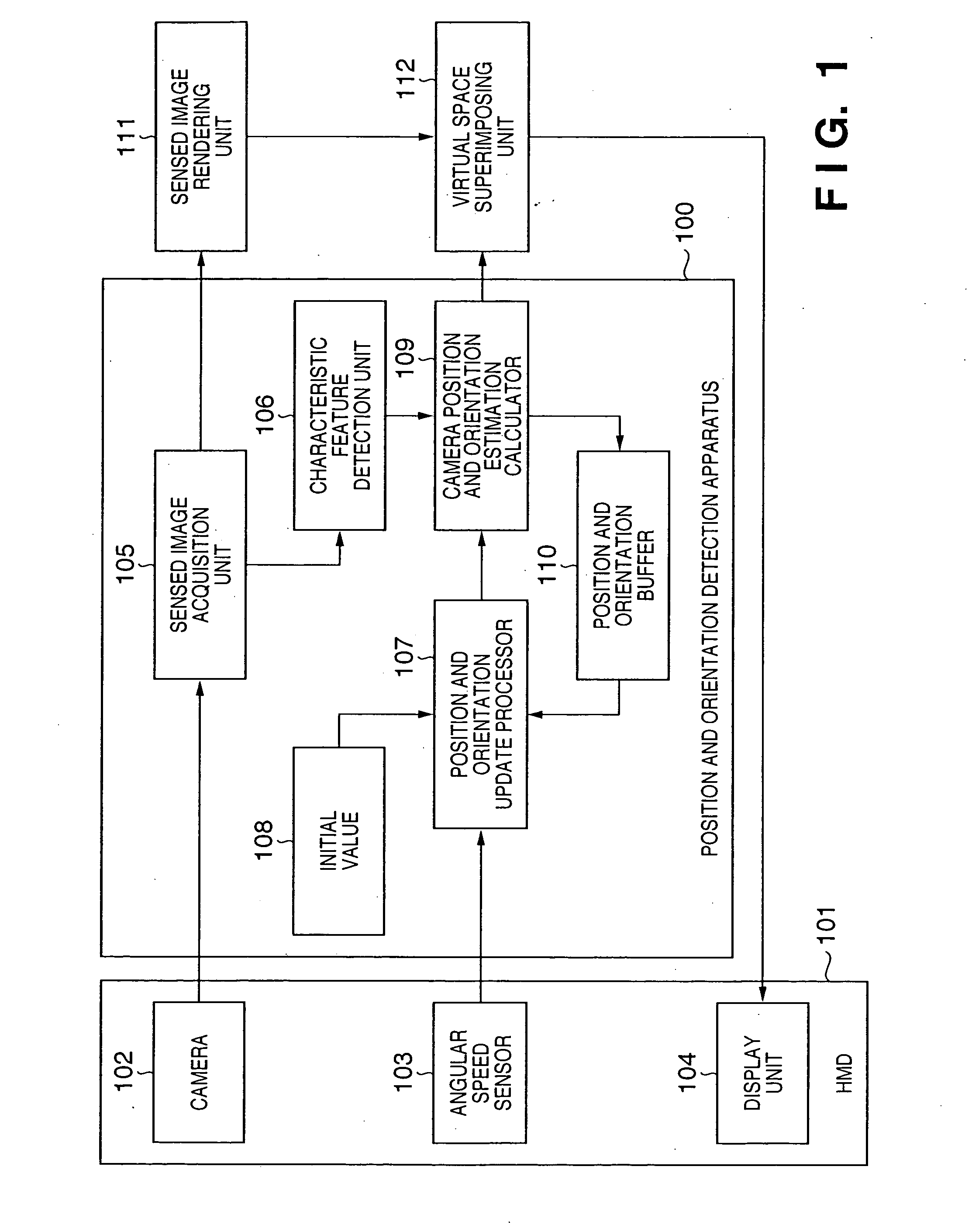
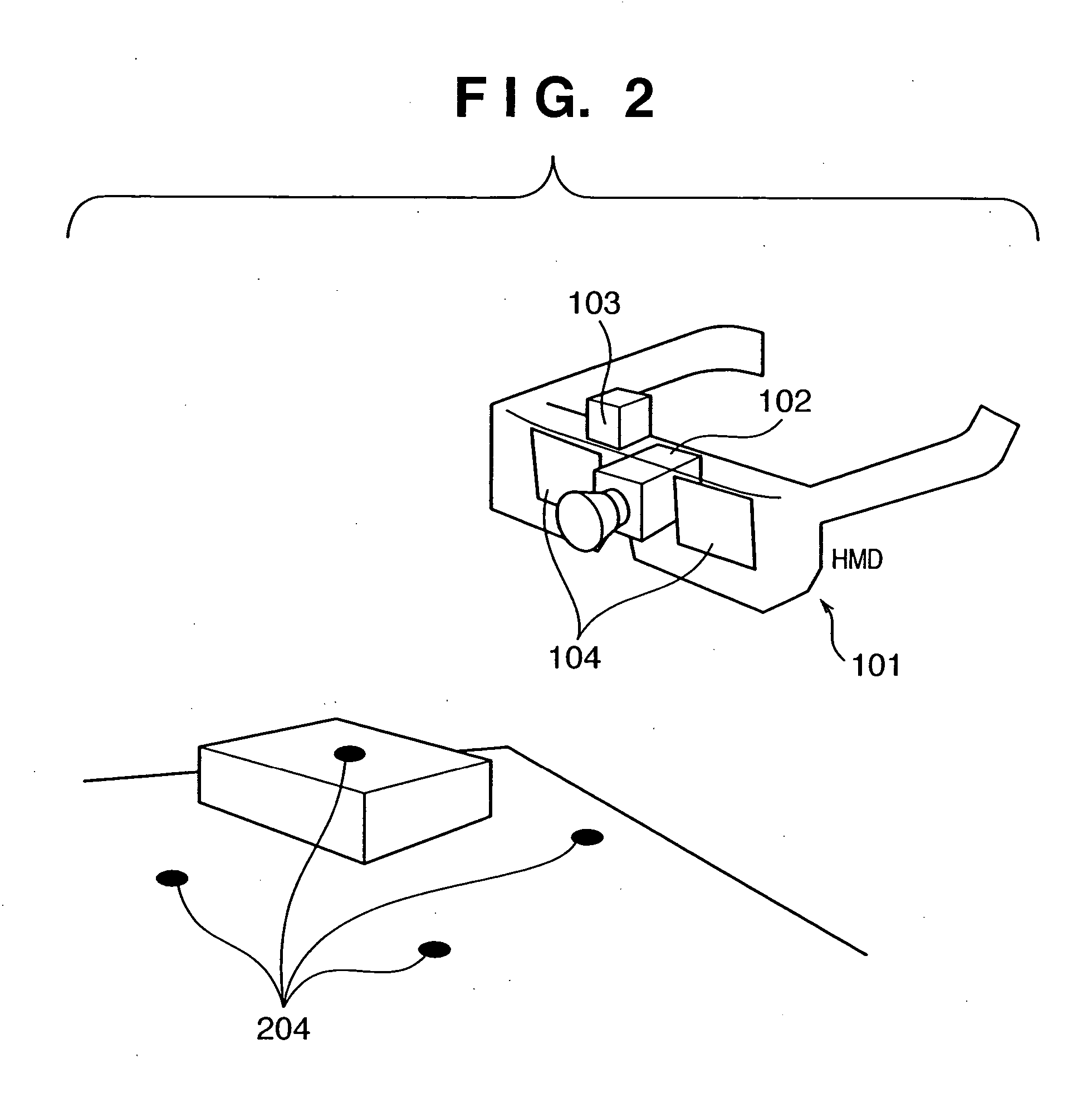
FIG. 1 shows the functional configuration of a case in which a position and orientation detection apparatus 100 according to the present embodiment is adapted to a Head Mounted Display (HMD) 101. The HMD 101 has a camera 102, an angular speed sensor 103 and a display unit 104, and can be moved through real space. The camera 102 senses the real space and outputs signals expressing a sensed image to a sensed image acquisition unit 105. The angular speed sensor 103, based on vibration gyro and other principles, detects the angular speed of movement of the HMD 101. The display unit 104 is a display unit capable of displaying an image, and is typically constructed of two display units, one for the right eye and one for the left eye.

It should be noted that although the present embodiment employs a HMD 101 of which the positions of each of the camera 102, the angular speed sensor 103 and the display unit 104 are fixed, provided that the positions of the camera 102 and t...


PUM


Abstract

The present invention provides a method and apparatus for inputting a signal indicating a change in position of an image sensing apparatus to predict present position and orientation of the image sensing apparatus using previously obtained position and orientation, by identifying corresponding pairs of indicators detected from an image in real space sensed by the image sensing apparatus and indicators contained in an image when sensed from a predicted position and orientation and using a correction method determined by the number of identified indicator pairs either to correct all or some of the degrees of freedom of the predicted camera position and orientation or to use the predicted camera position and orientation directly as is. As a result, highly accurate detection results can be obtained using a simple structure in the detection of the position and orientation of the image sensing apparatus.

Description

CLAIM OF PRIPRITY This application claims priority from Japanese Patent Application No. 2003-193633 filed on Jul. 8, 2003, the entire contents of which are incorporated herein by reference. FIELD OF THE INVENTION The present invention relates to position and orientation detection technique for detecting a position and orientation of an image sensing apparatus equipped with an image sensor for sensing images in real space and an orientation change detector for detecting the extent of a change in orientation. BACKGROUND OF THE INVENTION Detection of the position and orientation of an image sensing unit such as a camera that senses images in real space (hereinafter for convenience called simply “camera”) is necessary to a mixed reality system that combines real space and virtual space and displays combined space (hereinafter “mixed reality space”). As disclosed as conventional art in, for example, Japanese Laid-Open Patent Publication No. 11-084307 (publication no. 1), Japanese Lai...

Claims


Application Information

Patent Timeline
IPC IPC(8): G06T7/00G01B11/00H04N5/232
CPCG06T7/0018G06T2207/30244G06T7/0042G06T7/80G06T7/73
Inventor UCHIYAMA, SHINJISATOH, KIYOHIDE
Owner CANON KK
Why Eureka
Try Eureka