Transmission method and base transceiver station

a transceiver station and transmission method technology, applied in the field of transmission methods and base transceivers, can solve problems such as latent radio resources and difficulties in discontinuity

Active Publication Date: 2005-01-13
NOKIA TECHNOLOGLES OY
View PDF1 Cites 20 Cited by
  • Summary
  • Abstract
  • Description
  • Claims
  • Application Information

AI Technical Summary

Problems solved by technology

The discontinuity poses difficulties when a carrier subjected to the antenna hopping is required to provide correlated time slots, for example, for channel characterization purposes.
A portion of time slot

Method used


Image

  • Transmission method and base transceiver station
  • Transmission method and base transceiver station
  • Transmission method and base transceiver station

Examples


Embodiment Construction

:

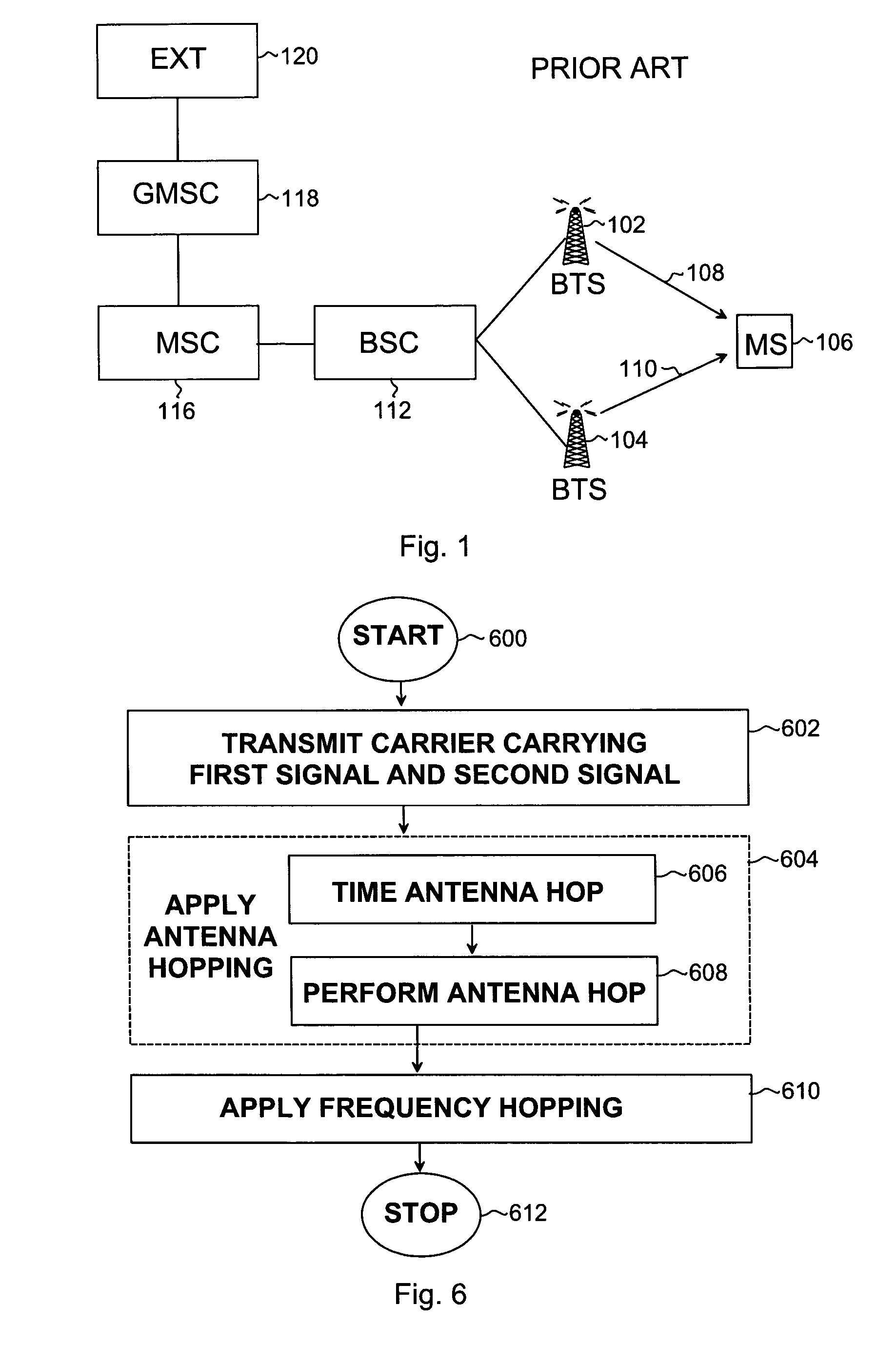
[0018]FIG. 1 illustrates an example of a simplified structure of a telecommunication system to which the invention may be applied.

[0019] The cellular telecommunications system is based on, for example, a GSM (Global System for Mobile Communications) radio access technology or WCDMA (Wideband Code Division Multiple Access) technology. The structure and function of cellular telecommunications systems are known to one skilled in the art, and only network elements relevant to the invention will be described.

[0020] In the example shown in FIG. 1, the network elements are presented in terms of GSM terminology using circuit-switched network elements without restricting applications of the invention to the GSM system.

[0021] The cellular telecommunication system may include a mobile switching center (MSC) 116 enabling circuit-switched signalling in the cellular telecommunications system.

[0022] In this embodiment, the cellular telecommunications system may also include a gateway mobile s...


PUM


Abstract

A transmission method and a base transceiver station applying antenna hopping between at least two antenna elements are provided. According to one embodiment of the invention, a carrier carrying a first signal and a second signal is transmitted. At least a portion of the first signal is subjected to a measurement for adjusting receive characteristics of a mobile station for the reception of at least a portion of the second signal. Antenna hopping is applied to the carrier such that the at least a portion of the first signal and the at least a portion of the second signal are transmitted during an interval between two consecutive antenna hops between the at least two antenna elements.

Description

BACKGROUND OF THE INVENTION: [0001] 1. Field of the Invention [0002] The invention relates to a transmission method and a base transceiver station in a cellular telecommunication system. [0003] 2. Description of the Related Art [0004] Transmit diversity, especially transmit antenna diversity, is an attractive means of obtaining diversity gain against fading mechanisms, such as Rayleigh fading, of a radio channel in telecommunications systems. An approach for providing diversity gain by way of antenna diversity is an antenna hopping method, which consists of transmitting consecutive information bursts from a base transceiver station by using different antennas. An antenna transmitting the information burst may be selected based on a periodical or pseudorandom antenna hopping sequence, for example. The gain in transmission is achieved provided that the radio channels transmitted from each antenna are exposed to different multi-path fading.[0005] A characteristic of the antenna hopping...

Claims


Application Information

Patent Timeline
IPC IPC(8): H04B7/06
CPCH04B7/0606
Inventor RANTA, PEKKA A.JOKINEN, HARRISAILY, MIKKONIEMELA, KARI
Owner NOKIA TECHNOLOGLES OY
Why Eureka
Try Eureka