
Threshing machinery concave arrangements

a technology of concave arrangement and thresher, which is applied in the field of threshers, can solve the problems of straw damage, straw becoming less suitable for some purposes, and breaking of stalks

Active Publication Date: 2005-01-13
BLUE LEAF I P INC +1
View PDF4 Cites 23 Cited by
  • Summary
  • Abstract
  • Description
  • Claims
  • Application Information

AI Technical Summary

Benefits of technology

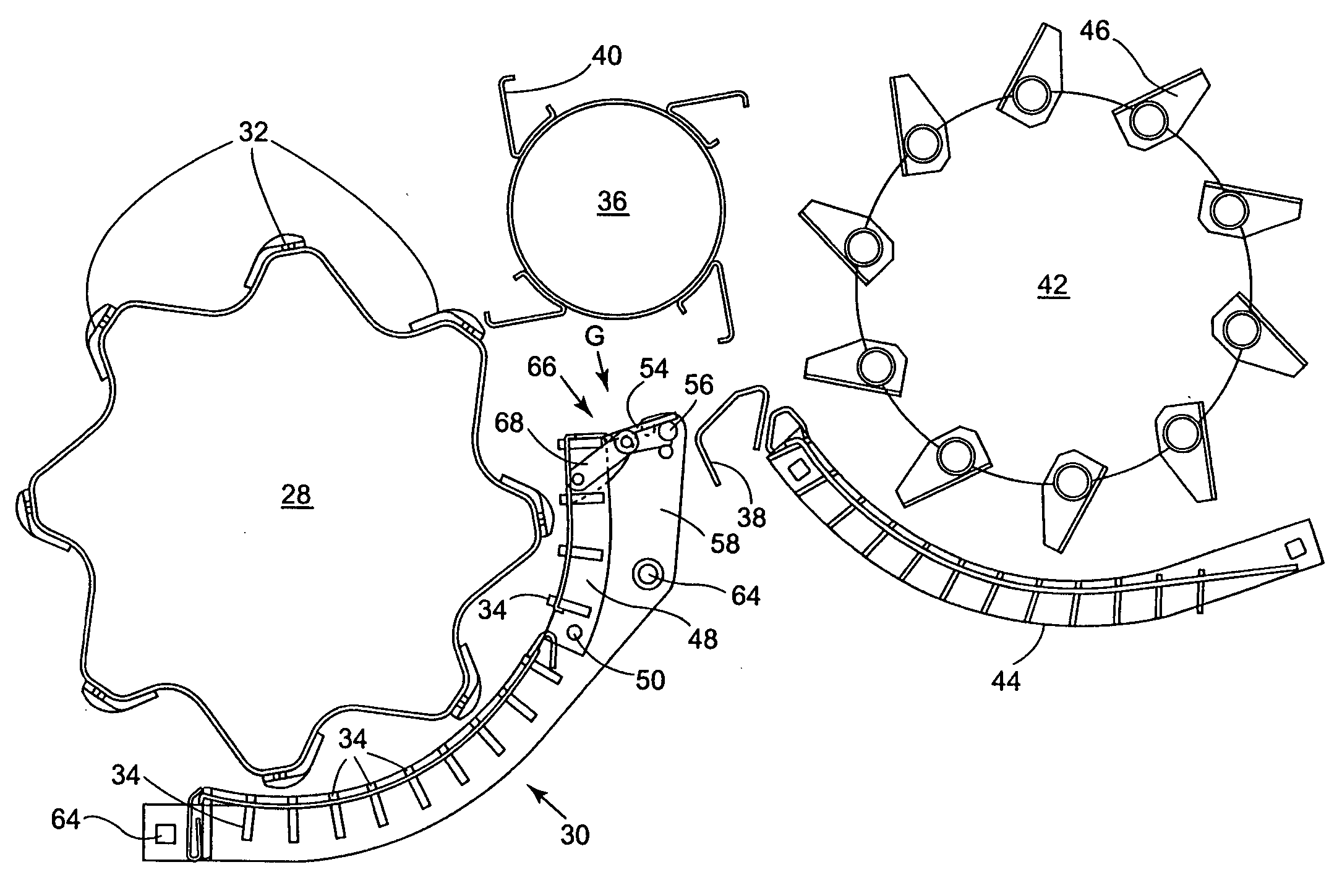
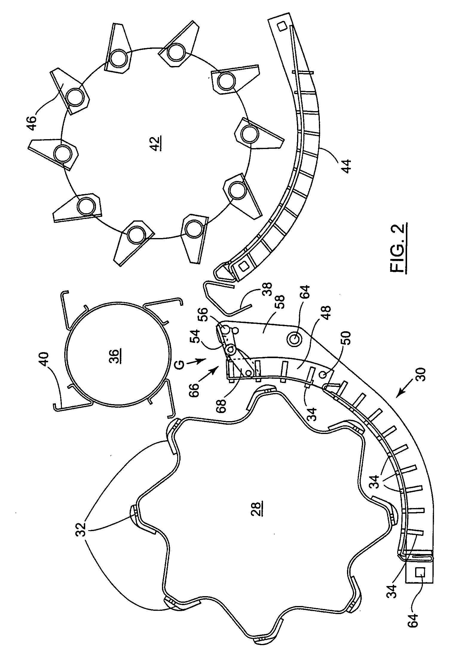
[0010] Accordingly, the present invention provides a concave arrangement for a threshing machine, the arrangement comprising a first stage having a concave associated with a rotary member, said concave having a hinged portion that is positioned in an exit region of said concave and is pivotally moveable between a first position and a second position so as to vary in use the distance between said hinged portion and said rotary member, said concave arrangement further comprising a second stage downstream of and spaced apart from said first stage and adapted to receive material processed in use in said first stage and said arrangement further including a bridging means for bridging a gap between said first and second stages, said bridging means being pivotally moveable jointly with said hinged portion such that said bridging means substantially closes said gap in and between each of at least said first and second positions of said hinged portion.
[0023] Movement of said hinged portion may be arranged in use to vary a break-over angle between two stages of crop processing, so as for example to control stalk breakage of crop passing between said stages.
[0026] The present invention also provides a method of processing gathered material using a concave arrangement comprising a first stage having a concave associated with a rotary member, the method including varying with a rearwardly disposed hinged portion of said concave a break-over angle presented to material between said first stage and a second stage and varying said break-over angle by moving said hinged portion jointly with a hinged bridging means in such a manner that said hinged bridging means substantially closes a gap between said first and second stages in a plurality of positions of said hinged concave portion.

Problems solved by technology

One problem that may arise involves straw damage and principally the breakage of stalks as threshed straw is passed over from a concave associated with a threshing drum to a concave associated with a beater or a rotary separator.
If this occurs to a significant extent, the straw becomes less suitable for some purposes, such as bedding for live-stock.
Moreover, short straw makes less neat and stable bales.
Furthermore an excess of short straw particles reduces substantially the efficiency of the straw walkers and / or other separation systems.
Broken straw may pass down through a gap between the concaves, thereby reducing efficiency of several stages of the cleaning procedure.
This creates a path by which cracked stalks and other chaff may potentially fall downward and decrease cleaning performance.
It also diminishes the separation capacity of a beater drum that is installed behind the threshing drum.

Method used


Image

  • Threshing machinery concave arrangements
  • Threshing machinery concave arrangements
  • Threshing machinery concave arrangements

Examples


Embodiment Construction

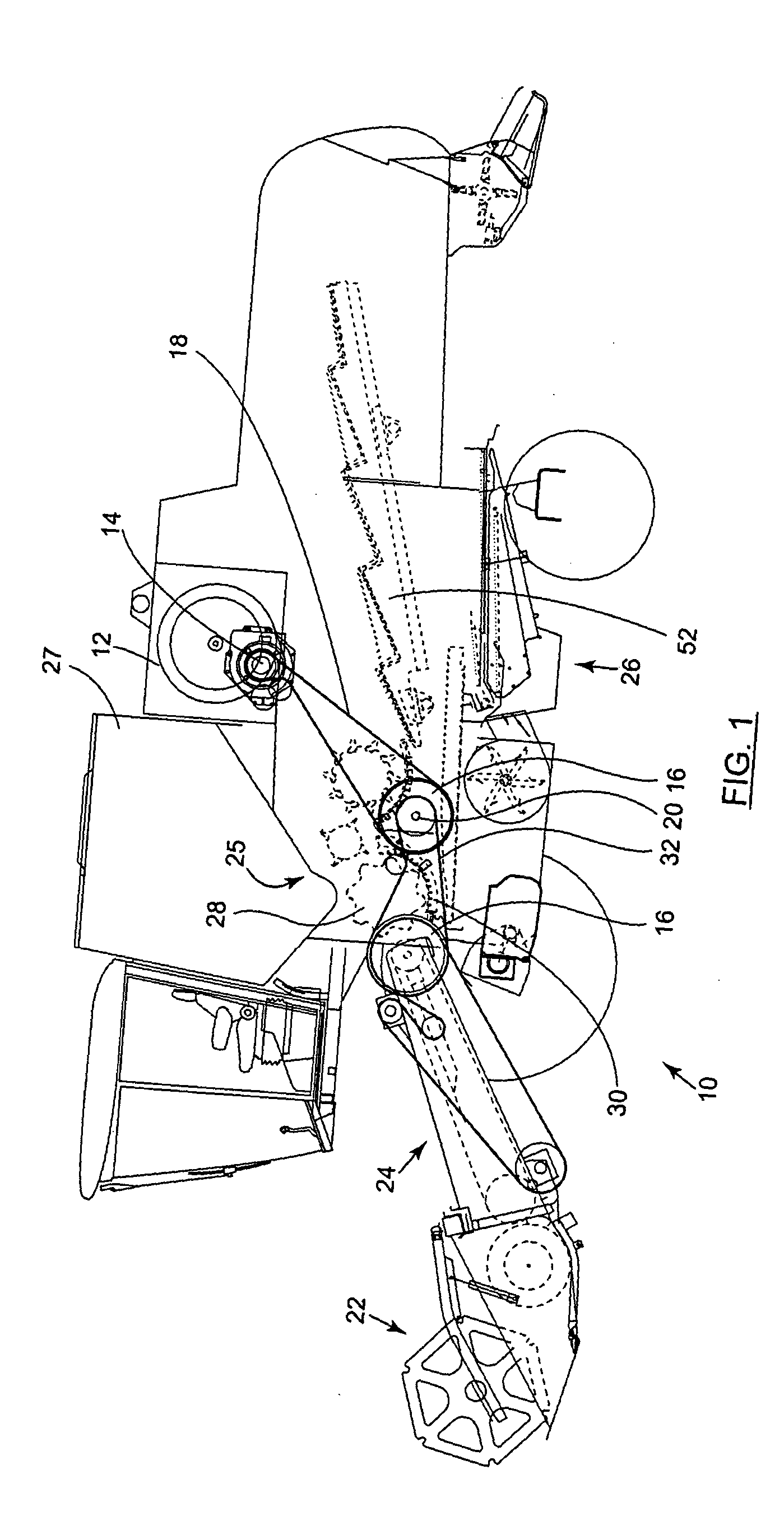
[0039] The present invention will now be described with reference to certain embodiments and with reference to the above-mentioned drawings. Such description is by way of example only and the invention is not limited thereto. Left and right references are used as a matter of convenience and are determined by standing at the rear of the threshing machine and facing the end forwards to the normal direction of travel. Likewise, forward and rearward references are determined by the normal direction of travel of the threshing machine. Upward or downward orientations and horizontal or vertical planes are relative to the ground or operating surface. In addition, while the terms “grain”, “straw” and “tailings” are used throughout the specification, this is principally for convenience and the terms are not intended to be limiting. Thus, “grain” refers to the part of gathered crop that is threshed and separated from the discardable part of the crop material, which is referred to as “straw”. I...


PUM


Abstract

A concave arrangement is disclosed for a threshing machine such as a combine harvester 10. The arrangement includes a concave 30 having a moveable rear portion 48 that is adapted to vary the break-over angle presented to straw passing downstream. A flap member 54 is provided that moves jointly with the moveable rear portion 48 and ensures that a gap G between the moveable portion 48 and a later processing stage such as a beater apparatus is kept substantially closed. Variation of the break-over angle influences the length of the straw leaving the threshing machine and the loading of the further separation and cleaning mechanisms.

Description

FIELD OF THE INVENTION [0001] The present invention relates to threshing machinery and in particular, but not exclusively, to improvements to concave arrangements associated with threshing and beating stages of a crop separation and / or cleaning operation in combine harvesters. BACKGROUND OF THE INVENTION [0002] A combine harvester usually includes a header attachment that is adapted to cut crop being harvested and that moves the harvested crop into a feeder housing. The feeder housing includes apparatus for lifting the cut crop into threshing and separation areas of the combine. Grain is then separated from stalks of the harvested crop by threshing, beating and possibly also rotary separation apparatus. The grain is then moved to a grain storage or distribution arrangement. Crop residue such as chaff and straw is commonly ultimately deposited onto the ground rearwards of the combine. [0003] Conventional threshing, beating and rotary separation apparatus typically involve feeding the...

Claims


Application Information

Patent Timeline
Patent Type & Authority Applications(United States)
IPC IPC(8): A01F12/28
CPCA01F12/28
Inventor DUQUESNE, FRANK R.G.JONCKHEERE, MARC R.M.LIPPENS, CHRISTIAAN A.C.DESNIJDER, DIRKDEVRIESE, THIERRY E.G.
Owner BLUE LEAF I P INC
Learn More