Management device for name of virtual port

Inactive Publication Date: 2005-01-13
HITACHI LTD
View PDF18 Cites 104 Cited by
  • Summary
  • Abstract
  • Description
  • Claims
  • Application Information

AI Technical Summary

Benefits of technology

[0008] This invention provides a method of maintaining and managing name information of a virtual port for preventing the situation as described above. To do so, a switch in accordance with the present invention adds information on a generat

Problems solved by technology

In a server which is required of high availability, it is not allowed to interrupt

Method used


Image

  • Management device for name of virtual port
  • Management device for name of virtual port
  • Management device for name of virtual port

Examples


first embodiment

[0030] the present invention will be described with reference to FIGS. 1 to 13. In the first embodiment, the case in which maintenance and management of name information of virtual ports are performed by lending and borrowing of the name information among plural switches in an SAN will be described.

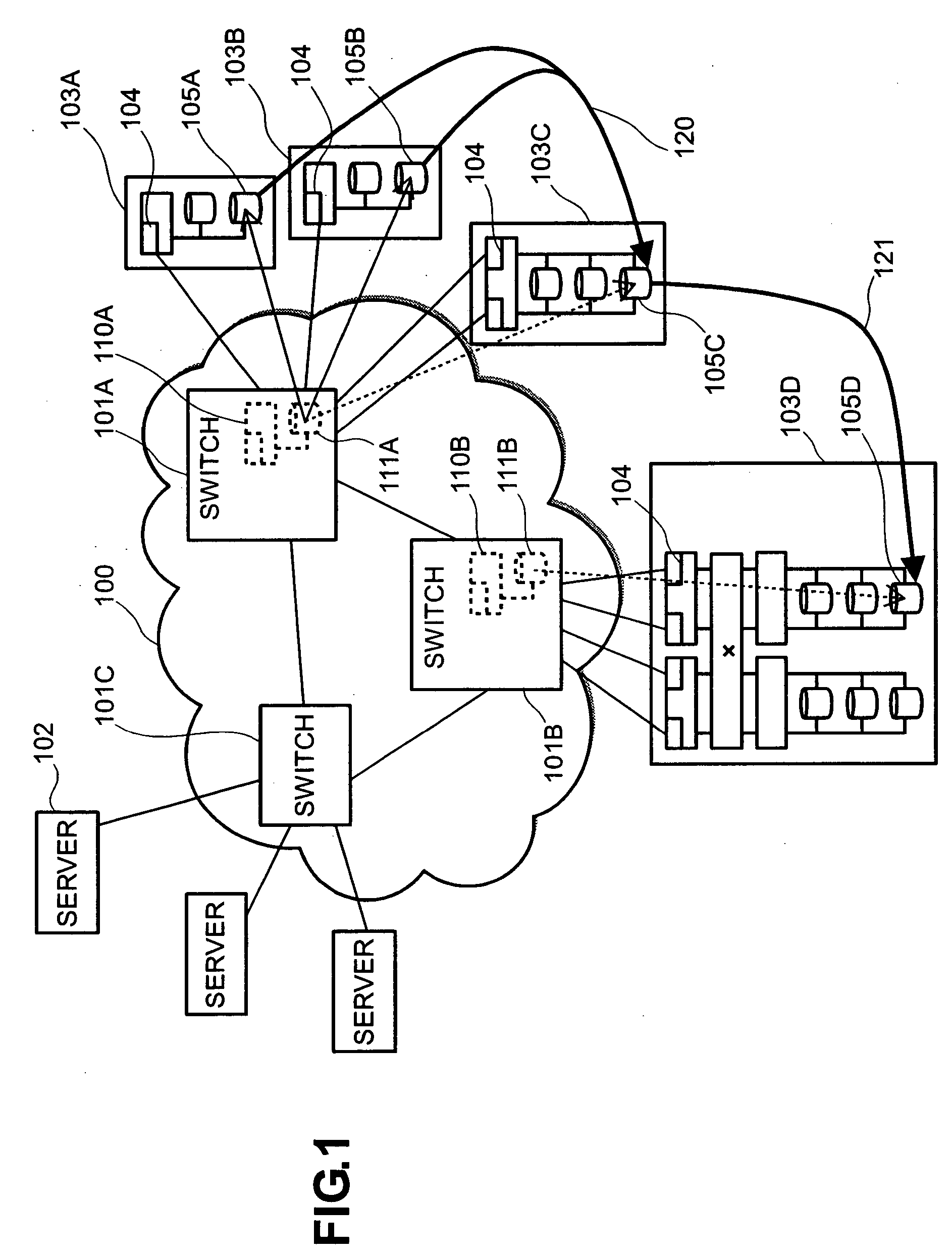
[0031]FIG. 1 is a diagram showing an example of a structure of an SAN including plural switches. The switches include FC switches and IP switches. An SAN 100 comprises plural switches 101A, 101B, and 101C (the switches will be hereinafter generally referred to as switch 101). A server apparatus (hereinafter referred to as server) 102 is connected to the switch 101C. Examples of the server include a UNIX server, a PC server, and a mainframe. In FIG. 1, storage systems 103A, 103B, and 103C are connected to the switch 101A, and a storage system 103D is connected to the switch 101B (the storage systems will be hereinafter generally referred to as storage system 103). Note that types of the st...

third embodiment

[0076] Next, the present invention will be described with reference to FIGS. 19 and 20. Here, an example in which the structure of the switch of FIG. 2 is included in the structure of the storage system shown in FIG. 4 will be described.

[0077]FIG. 19 is a diagram showing an example of a structure of a storage system such as a RAID apparatus incorporating a switch function. A storage system 1901 comprises: plural link interfaces 1902A which control a physical layer and a data link layer of a Fibre Channel for connecting the switch 101, the server 102, and the storage system 103; plural link interfaces 1902B which control a physical layer and a data link layer of the Ethernet; plural link interfaces 1902C for accessing a storage on a file base such as a network attached storage (NAS); plural routing processor 1903 as in FIG. 2, plural disk adapters 1906 for accessing the plural storage devices 304; plural cache adapters 1905 which control a cache memory for each disk adapter 1906; the...


PUM


Abstract

A method is provided with which a name of a virtual port is not changed when virtualized storage is moved among switches. Information about a creator and a borrower of name information is added to a table including name information and address information of a virtual port of a name server managing the name information and the address information. The name information is provided to plural switches and managed. In addition, name information, which can be used commonly among name servers managing the name information and the address information is pooled in advance, and the name information of the virtual port is borrowed from there.

Description

BACKGROUND OF THE INVENTION [0001] 1. Field of the Invention [0002] The present invention relates to a switch-based (storage) virtualization technique in a storage area network (SAN), and relates to a management method for a name which is given to a port of a switch providing a virtualized storage. [0003] 2. Description of the Prior Art [0004] In the Fibre Channel (FC)-SAN environment, or the IP-SAN environment using the internet Small Computer System Interface (iSCSI) obtained by encapsulating the Small Computer System Interface (SCSI) in the Transmission Control Protocol / Internet Protocol (TCP / IP), an apparatuses such as a server or a storage is treated as a node. To identify a node in the SAN, in the FC-SAN each node has 24-bit address information called a port ID and 64-bit name information called a World Wide Name (WWN) by a unit of port. In addition, in the IP-SAN, each node has 32-bit address information in Ipv4 or 128-bit address information in Ipv6 called an IP address, 48-...

Claims


Application Information

Patent Timeline
IPC IPC(8): G06F13/10G06F3/06G06F12/00G06F13/40G06F15/16
CPCG06F13/4081
Inventor MURAKAMI, TOSHIHIKOKUMAGAI, ATSUYAIWAMI, NAOKO
Owner HITACHI LTD
Why Eureka
Try Eureka