Machine and method for processing textile fabrics

Inactive Publication Date: 2005-01-20
CORAMTEX
View PDF18 Cites 0 Cited by
  • Summary
  • Abstract
  • Description
  • Claims
  • Application Information

AI Technical Summary

Benefits of technology

Object of the present invention is the realization of a new method and machine to overcome the aforesaid problems. More in particular, object of the invention is the realization of a machine for processing—specifically abrasion processing—textile materials or other continuous web material without inducing tensions in the web material which may negatively affect the final processing result.
According to a practical embodiment the method according to the invention provides for: arranging a mobile guiding element for the web material along the feeding path next to the cylindrical member; detecting the position of the mobile guiding element with respect to the cylindrical member; and controlling the speed at which said web material is distanced and / or fed to the cylindrical member according to the position of the mobile guiding element.

Problems solved by technology

Tensioning the material causes a number of problems, particularly due to the formation of folds or creases in the longitudinal direction which leads to the fabric being processed in different ways along its transversal development.
The tension induced in the fabric may also alter the structure of the warp and weft yarns with consequent processing irregularities.
Some yarns are subjected to more abrasion than others causing the formation of irregularly distributed lines on the finished product, in correspondence to where the fabric was excessively consumed by the abrasive member and appears to have lost essentially all its color.
The loose or taut selvages subjected to tension by traditional grinding machines cause problems related to variable degree of abrasion which affects processing quality;
When the textile fabric, the non-woven or other web material is turned on a rotating abrasive cylinder without being adequately tensioned, the friction between the web material and the surface of the rotating cylindrical member tends to make the web material wind around the cylindrical member itself.
The web material must be kept taut, which causes the aforesaid problems, to avoid jamming the machine.

Method used


Image

  • Machine and method for processing textile fabrics
  • Machine and method for processing textile fabrics
  • Machine and method for processing textile fabrics

Examples


Embodiment Construction

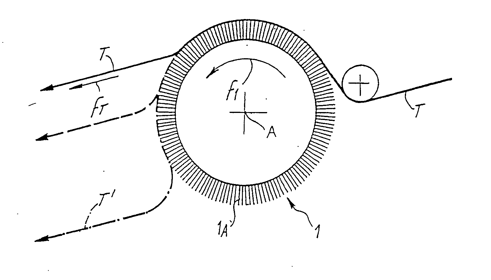
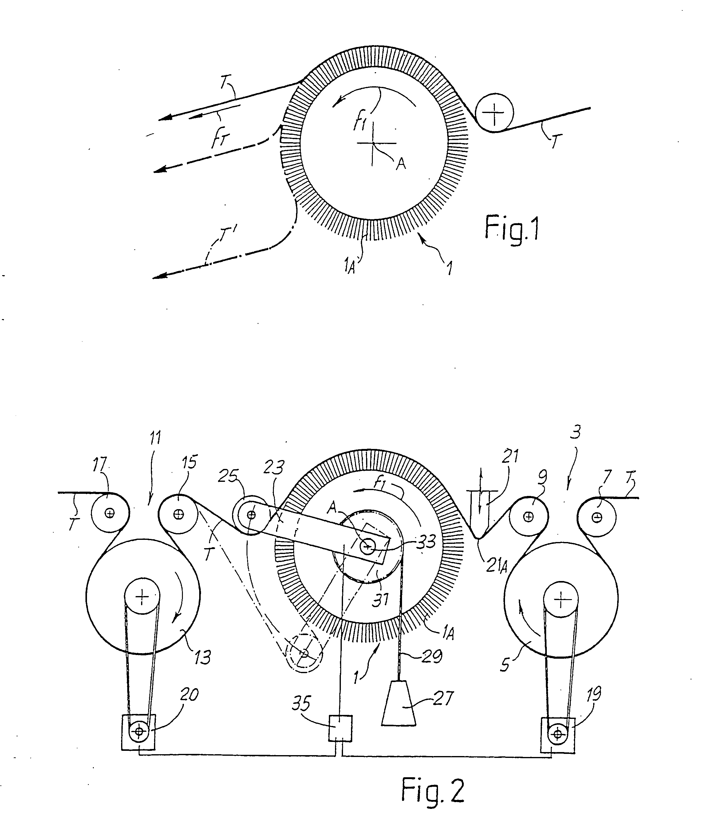
Reference numeral 1 in FIG. 1 very schematically indicates an abrasive rotating cylindrical member, specifically an abrasive cylindrical brush in this example. The cylindrical member turns on an axis A in the direction indicated by the arrow f1. Reference 1A indicates a clothing, for example, made of filaments of synthetic material charged with abrasive particles, e.g. TYNEX® filaments.

A textile fabric T advancing the arrow fT is guided around the rotating cylindrical member 1. As shown in FIG. 1, the trajectory of the fabric T can vary according to the contact arch on the cylindrical member 1. By reducing the tension on the textile fabric T, the latter is dragged downwards by the cylindrical member 1, whose peripheral speed is higher than the speed of advancement of the fabric itself. Excessively low stress on the textile fabric T makes the fabric tend to wind around the rotating cylindrical member 1, as shown by the fabric in the attitude indicated by reference T′.

This proble...


PUM


Abstract

The machine comprises: an advancement path of said web (T); at least one abrasive member, essentially cylindrical, rotating and abrasive (1) the advancement path on which the material is guided; a means (3) for feeding said web material to said cylindrical member; and a means for distancing (11) said web material from said cylindrical member. The cylindrical member is associated a mobile guiding element (23, 25) on which the web material is guided, whose position varies with the variation of the contact arch between the web material and the cylindrical member. The speed of at least one of said feeding and distancing means is controlled according to the position of said mobile guide element.

Description

TECHNICAL FIELD The present invention relates to a machine for processing textile fabrics and more in general for processing web material. Specifically, the invention relates to a machine for processing web material comprising an advancement path of the web and an essentially cylindrical rotating abrasive member which acts on the web, which is entrained around the member itself. STATE OF THE ART Machines in which continuously fed textile fabric is subjected to finishing and aging processes by means of abrasive material applied onto a rotating cylinder, around which the textile material is entrained, are employed in the fabric processing. The surface of the textile fabric is mechanically processed by exploiting the different speeds of the abrasive surface of the cylinder and of the textile fabric. U.S. Pat. No. 3,615,990 describes a machine for processing textile fabric or non-wovens by means of rotating cylindrical brushes. The web is tensioned and passed under the brushing memb...

Claims


Application Information

Patent Timeline
IPC IPC(8): B65H20/24D06C11/00
CPCD06C11/00B65H20/24B65H23/16
Inventor MARCORA, LUIGICIABATTINI, ALBERTO
Owner CORAMTEX
Why Eureka
Try Eureka