Conductive pressure sensitive textile

a technology of conductive pressure and textiles, applied in the direction of insulated cables, leno-woven fabrics, insulated conductors, etc., can solve the problems of fabric thickness, additional cost, three or more fabric layers, etc., and achieve the effect of cheaper production

Inactive Publication Date: 2008-04-29
INTELLIGENT TEXTILES
View PDF78 Cites 161 Cited by
  • Summary
  • Abstract
  • Description
  • Claims
  • Application Information

AI Technical Summary

Benefits of technology

[0020]The preferred embodiments of fabric can be significantly cheaper to p

Problems solved by technology

Although such fabric assemblies can function well, there are inevitable drawbacks with having to have three or more fabric layers, includ

Method used


Image

  • Conductive pressure sensitive textile
  • Conductive pressure sensitive textile
  • Conductive pressure sensitive textile

Examples


Embodiment Construction

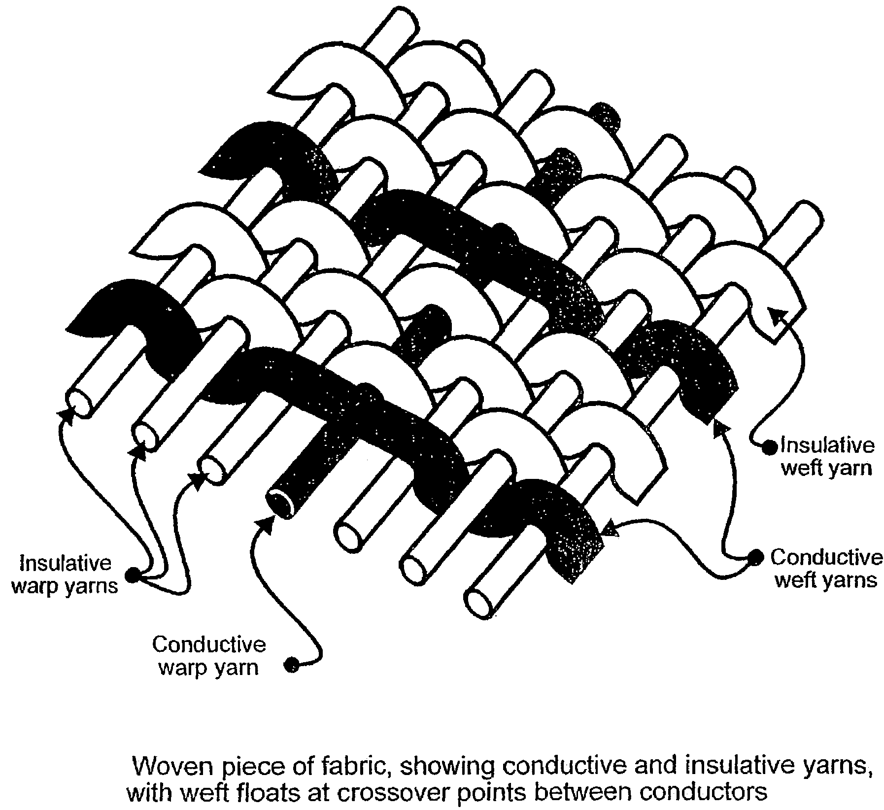
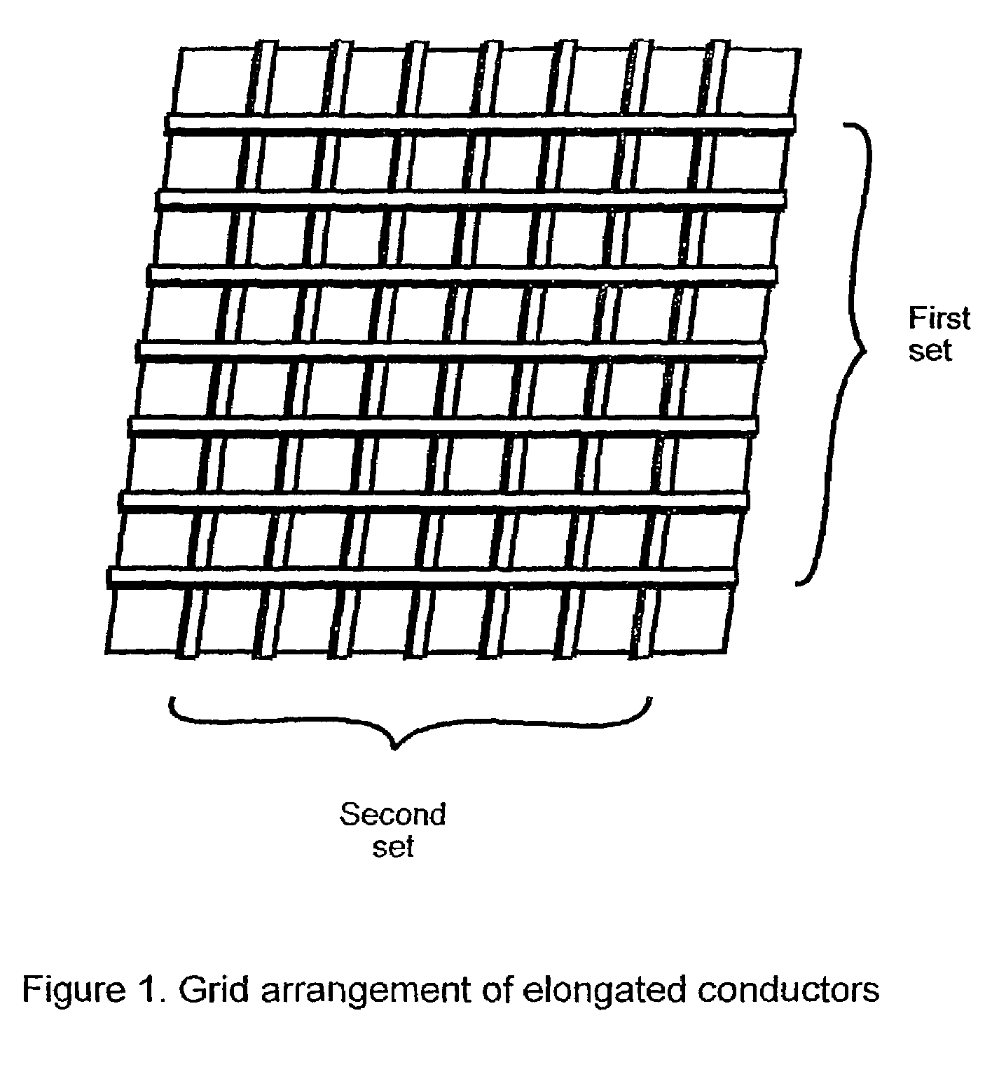
[0034]Referring to the Figures, in the embodiment of FIG. 1, the piece of fabric preferably comprises at least two sets of elongate electrical conductors. Typically, the conductors in each set are arranged in parallel relative to one another and one set of conductors is arranged perpendicular relative to the other set to form an arbitrarily spaced grid, as shown in FIG. 1. The elongated electrical conductors are typically mono-filament or multi-filament conductive fibres, while the remainder of the piece of fabric is composed of insulating fibres.

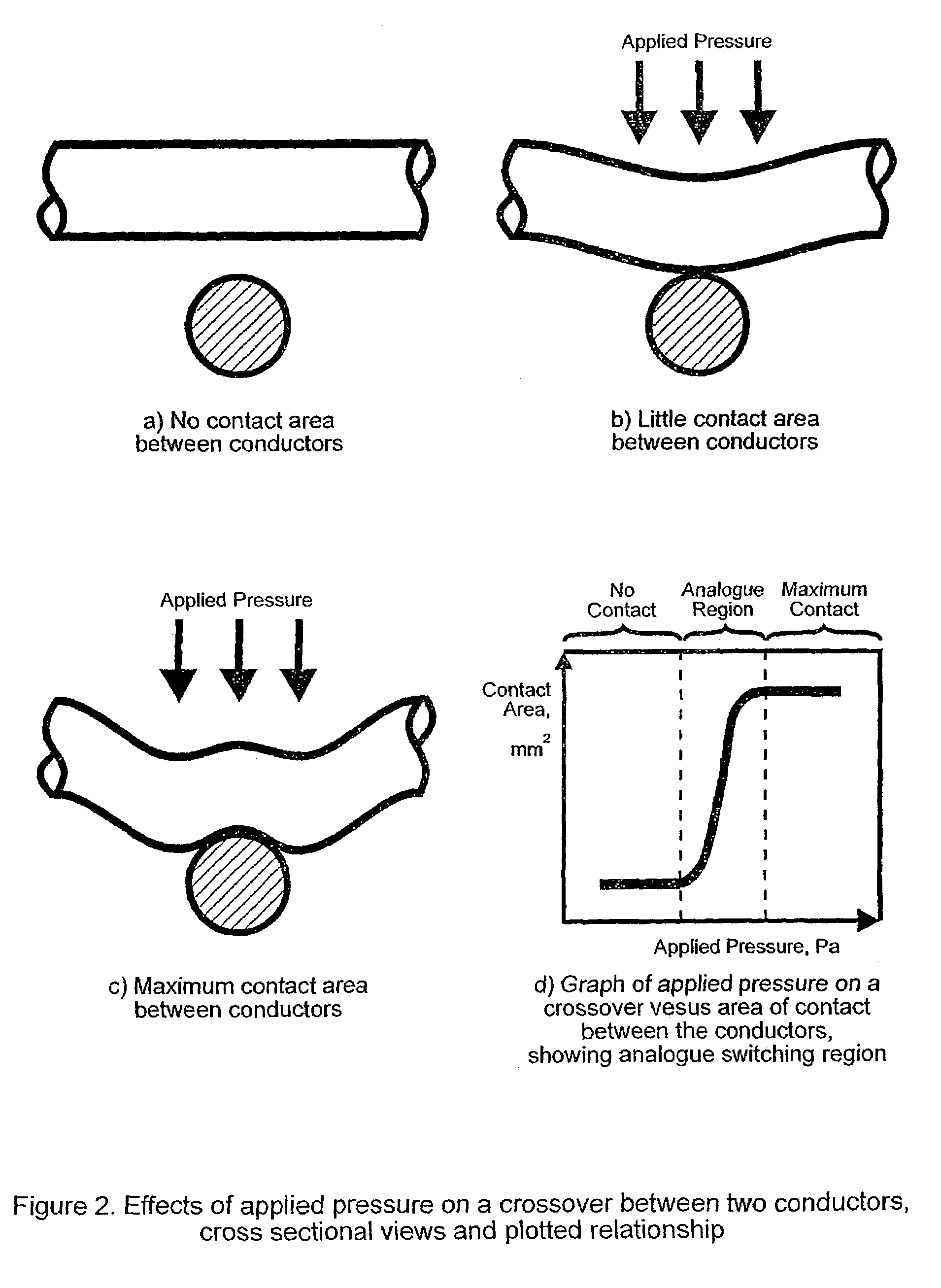
[0035]Where any two conductors cross over one another, the construction of the fabric and / or the conductive fibres maintains their physical separation, as shown in the cross-sectional view of two conductors in FIG. 2(a). When pressure is applied normal to the plane of the fabric, the conductive fibres are caused to deflect and make electrical contact, as in FIG. 2(b). Thus, each crossover point constitutes a momentary contact electrical swi...


PUM

PropertyMeasurementUnit
Timeaaaaaaaaaa
Lengthaaaaaaaaaa
Pressureaaaaaaaaaa

Abstract

A fabric including within its construction a first elongated electrical conductor crossed by a second elongated electrical conductor, the conductors being normally biased apart at a crossover point of said fibres with an air gap between them, whereby application of pressure in a direction substantially normal to a plane of the fabric causes the conductors to make contact. The fabric may be woven, knitted, non-woven or plaited. The fabric can be used as a pressure sensor, switch or other sensor.

Description

FIELD OF THE INVENTION[0001]The present invention relates to methods of constructing one or more pressure activated electrical switches or sensors in fabric, in the preferred embodiment as integral elements of a single fabric sheet.BACKGROUND OF THE INVENTION[0002]Electrically conductive fabric sheets are known in the art and are described, for example in the applicant's earlier British patent application 2,339,495. The known conductive fabric sheets typically comprise two conductive layers separated by an insulating layer which can be bridged upon application of pressure on the conductive layers. Although such fabric assemblies can function well, there are inevitable drawbacks with having to have three or more fabric layers, including additional cost, fabric thickness, need to maintain alignment between the various layers, movement of the layers during use and so on.SUMMARY OF THE INVENTION[0003]The present invention seeks to provide an improved conductive textile. According to an ...

Claims


Application Information

Patent Timeline
IPC IPC(8): D03D15/00D02G3/12D02G3/38D02G3/44G01L1/20G06F3/033G06F3/045H01H1/06H01H13/52H01H13/70
CPCD02G3/38D02G3/441G01L1/20G06F3/045Y10S2/902H01H2203/01Y10T428/2915Y10T428/2936Y10T428/2913H01H2203/0085Y10T442/3114Y10T442/3976Y10T442/109Y10T442/162Y10T442/3098Y10T442/3382Y10T442/3089Y10T442/3122Y10T442/641Y10T442/30Y10T442/68Y10T442/642Y10T442/682Y10T442/3179Y10T442/339Y10T442/313Y10T442/654Y10T442/649Y10T442/3293
Inventor SWALLOW, STANLEY SHIGEZOPETA-THOMSON, ASHA
Owner INTELLIGENT TEXTILES
Why Eureka
Try Eureka