Long life piezoelectric drive and components

Inactive Publication Date: 2005-01-20
BRADY GRP INC THE +1
View PDF12 Cites 28 Cited by
  • Summary
  • Abstract
  • Description
  • Claims
  • Application Information

AI Technical Summary

Benefits of technology

[0009] According to one aspect of the present invention, a piezoelectric drive, and its components (particularly rotors and/or pushers thereof), are provided that overcome the problems inherent in the conventional prior art discussed above, and can be advantageous compared to the structure of the EPO reference. The piezoelectric drives, and components, according to the invention have significantly reduced wear of the pushers and rotors, resulting in longer life. For example, a piezoelectric drive according to the invention having a rotor according to the invention can be expected to have an effective life of over about 6000 hours of actual operation, e. g. about 7000 hours. If pushers according to th

Problems solved by technology

However, such conventional hard materials used for rotors, especially when used with steel pushers, are very abrasive.
The abrasive action between the pushers and rotors causes rapid wear of the rotor and pusher materials, fine particles of the rotor and pushers breaking off.
When the broken-off steel particles are exposed to air they typically oxidize, e. g. turning into a hard abrasive powder of iron oxide.
This means that conventional piezoelectric drives have an effective life of only about 100-1000 hours of actual operation, too short for many applications (including, but not limited to, analog instruments).
The fine particles of iron oxide cause other problems.
The combination of wear and penetration causes a non-uniform rotor surface, resulting in an inexact degree of rotation of the rotor for each actuation of the piezoelectric oscillator.
This limits applicability of conventional piezoelectric drives in applications (including, but not limited to, analog instruments and servo systems) where drive precision is necessary.
Yet another weakness inherent in rotors made from materials like steel, alumi

Method used


Image

  • Long life piezoelectric drive and components
  • Long life piezoelectric drive and components
  • Long life piezoelectric drive and components

Examples


Example

DETAILED DESCRIPTION OF THE DRAWINGS

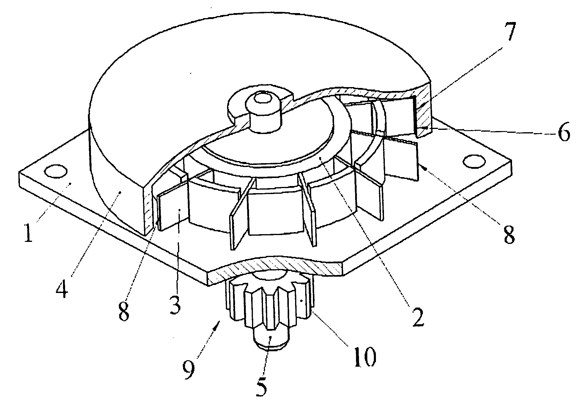
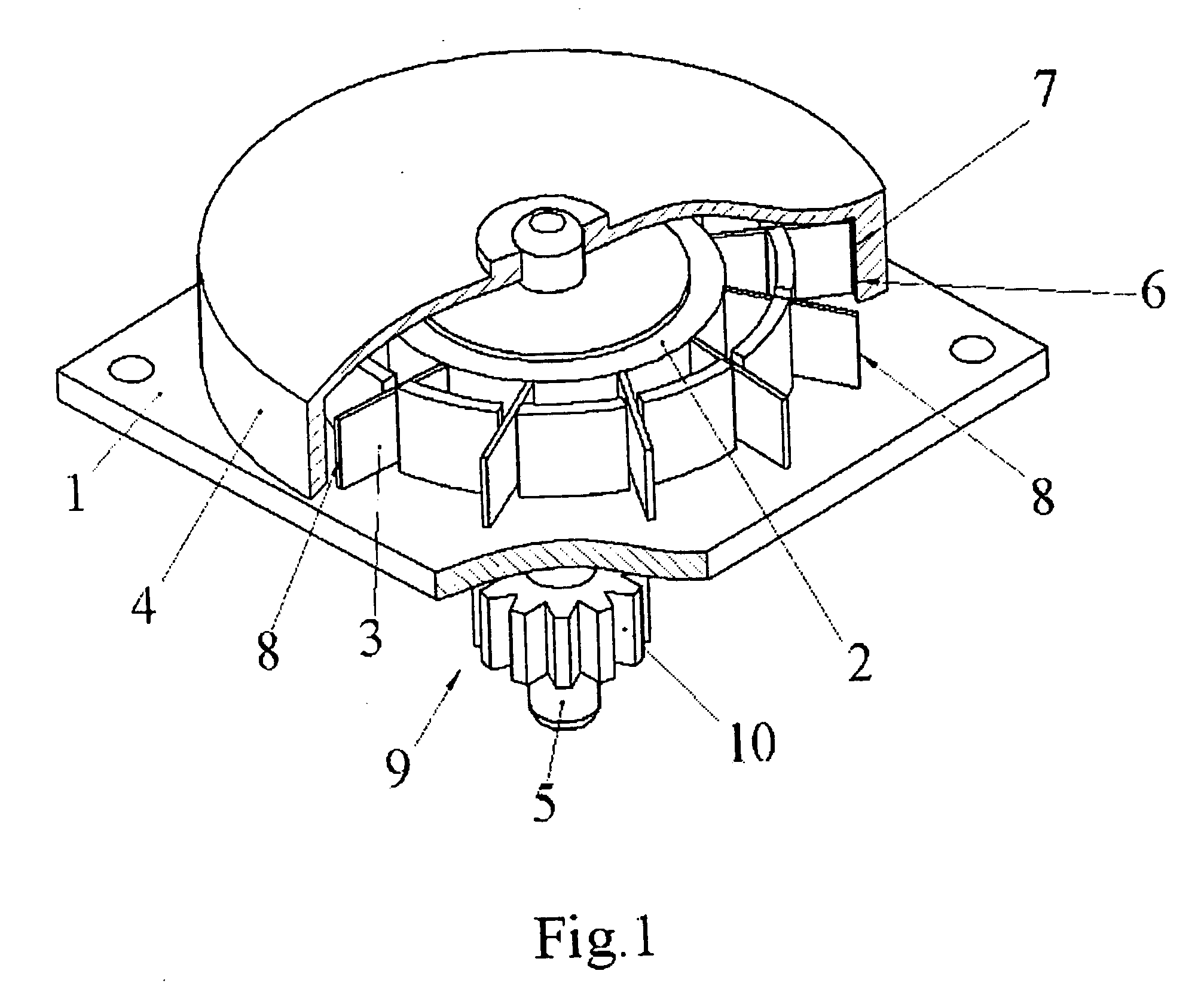
[0040] An exemplary unidirectional piezoelectric drive according to the present invention is illustrated in FIG. 1. The components include a stator 1, a conventional piezoelectric oscillator 2, a plurality of elastic pushers 3, and a rotor 4. All of these components are known per se in conventional piezoelectric drives. According to the present invention, the material and configuration of the construction of the rotor 4 and / or pushers 3 results in numerous advantages (including long life, enhanced precision, and reduced cost) compared to conventional piezoelectric drives.

[0041] In the embodiment illustrated in FIG. 1, the rotor 4 is generally cup-shaped, and is operatively (e. g. rigidly) attached to a shaft 5, which the rotor 4 drives. The inner surface 6 of the rotor comprises a friction surface 7, which surface 7 engages the free, frictional, ends 8 of the pushers 3. The pushers 3 are operatively connected to the oscillator 2. An executive el...


PUM


Abstract

A piezoelectric drive, and the rotor and/or pushers thereof, have long life, e. g. at least about 6000 hours of actual operation. The piezoelectric drive also is highly accurate, and is relatively inexpensive to make. The rotor friction surface and/or pushers are made from a material having a low mechanical quality factor, yet with high strength and stability under the conditions encountered in the ultrasonic fields typical of piezoelectric drives. The material is preferably a semi-crystalline thermoplastic polymer (e. g. polyarylamide) with filler (e. g. glass particles or fiberglass), e. g. about 30-60% polymer and about 40-70% filler, and can easily make injection molded components or parts or components. A pair of drives may be connected together to form an instrument, for example rotating a shaft connected to a pointer of analog instrument either clockwise or counterclockwise. Analog instruments, such as thermometers, barometers, speedometers, altimeters, pH meters, anemometers, etc., or other precision devices may utilize the piezoelectric drive. Alternatively, the piezoelectric drive may drive other mechanical devices such as gears, encoding locks, servo systems, point of purchase devices, micro pumps, clocks, timers, etc.

Description

[0001] The invention relates to a piezoelectric drive (also sometimes referred to as a piezoelectric motor) having components, including a rotor and / or pushers, which give it long life and a number of other advantages compared to conventional piezoelectric drives. The piezoelectric drive according to the invention is suitable for use in the construction of analog instruments, as well as for driving a wide variety of other devices including (without limitation) gears, point of purchase displays, encoding locks, and micro-pumps, and the invention also encompasses unique instruments and devices per se. BACKGROUND AND SUMMARY OF THE INVENTION [0002] One of the most basic aspects of the present invention relates to a piezoelectric drive of the general type such as shown in U.S. Pat. Nos. 4,400,641, 4,453,103, 4,959,580 and 6,469,420 (the disclosures of which are hereby incorporated by reference herein). Such drives have a rotor, stator, a piezoelectric oscillator, and elastic pushers act...

Claims


Application Information

Patent Timeline
IPC IPC(8): H01L41/08H01L41/09H02N2/00H02N2/10H02N11/00
CPCH02N2/002H02N2/0065H02N11/006H02N2/103H02N2/007
Inventor BRADY, KEVINVYSHNEVSKYI, DMYTROHAMBERGER, GYULANUNES, BRENDON
Owner BRADY GRP INC THE
Why Eureka
Try Eureka