
Method of regulating output parameters of a power supply

a technology of output parameters and power supply devices, applied in the direction of three-or-more-wire dc circuits, circuit arrangements, instruments, etc., can solve the problems of inability to calibrate the power supply device, inability to measure, and inability to live up to error margins in many cases, so as to reduce tight error margins

Inactive Publication Date: 2005-01-20
KONINKLIJKE PHILIPS ELECTRONICS NV
View PDF4 Cites 4 Cited by
  • Summary
  • Abstract
  • Description
  • Claims
  • Application Information

AI Technical Summary

Benefits of technology

The present invention provides a method and device for regulating the output of a power supply device to a load device, which helps to reduce tight error margins. The method involves delivering a control signal from the load device to the power supply device, regulating the output parameter value in the power supply device in response to the control signal, and delivering the regulated output parameter value to the load device. This feedback loop helps to ensure accurate and reliable delivery of the required parameter value. The invention also provides a display device that includes a load device, which allows for optimal picture quality and reduced costs of manufacturing. Overall, the invention provides a more efficient and cost-effective solution for delivering power to loads.

Problems solved by technology

In some power supply devices of today these specified error margins can in many cases be hard to live up to.
Also the use of the sticker poses problems, such as: calibration of the power supply device using the sticker value cannot be done before assembly of the total monitor, so it would have to be done after assembly.
After assembling the monitor, it is often impossible to calibrate the power supply device, since, for example, the sustain and addressing voltages cannot be reached anymore, so they cannot be measured.

Method used


Image

  • Method of regulating output parameters of a power supply
  • Method of regulating output parameters of a power supply
  • Method of regulating output parameters of a power supply

Examples


Embodiment Construction

The present invention relates generally to load devices having special requirements on the power supply. The present invention also relates to a display device having such a load device as well as a method of regulating a power supply device.

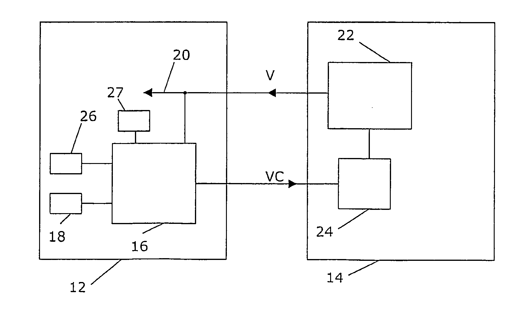
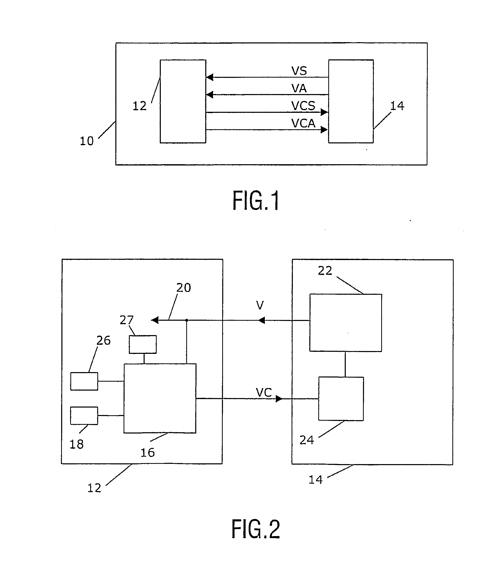
In FIG. 1 is shown a block schematic of a display device according to the prior-art. The display device according to a preferred embodiment of the invention is a television set 10 having two separate entities, one being a load in the form of a PDP (plasma display panel) screen 12 separated from and connected to another entity in the form of a power supply device 14. The power supply device 14 can in a known way be connected to a power network in order to perform power conversion for supply to the PDP screen 12. The plasma display panel 12 requires accurate voltages like a sustain voltage VS and addressing voltage VA, which are used for energizing the screen. The power supply device 14 supplies these voltages via two lines. These voltages have...


PUM


Abstract

The present invention relates to a method, load (12) and display device (10) where an output parameter value (V) of a power supply (14) coupled to a separate load (12) is regulated. The load (12) demands at least one such parameter value (V) from the power supply (14). The power supply (14) delivers the output parameter value (V) to the load (12). The load (12) comprises a control signal setting unit (16), which receives information relating to the output parameter value (V) and is connected to the power supply (14) for delivering a control signal (VC). The control signal (VC) includes information relating to the output parameter value (V) and is used by the power supply (14) for regulating the output parameter value (V). This makes the control signal setting unit (16) part of a feedback loop. The parameter value is preferably an output voltage, the load a plasma display panel and the display device a television set.

Description

TECHNICAL FIELD The present invention relates to the field of power supplies for electrical loads. DESCRIPTION OF RELATED ART There has in recent years been a development of load devices, which have more severe requirements on the voltages and / or currents delivered to them in order to function properly. One such device is a plasma display panel. A plasma display panel (PDP) requires accurate voltage levels from a power supply device for the sustain voltage and the addressing voltage used in the display. A current system consists of two methods: According to a first method the PDP delivers two different reference voltages ranging between 0 and 2 V, to be used for controlling sustain and addressing voltages. The power supply device then has to deliver output values derived from these reference voltages via a predefined formula. Another method suggests that required sustain and addressing voltages are printed on a sticker on the PDP. These values can then be used by a set maker to c...

Claims


Application Information

Patent Timeline
Patent Type & Authority Applications(United States)
IPC IPC(8): G09G3/20G09G3/28G09G5/00H02J1/08
CPCG09G3/28H02J1/08G09G2330/02G09G5/00G09G3/288G09G3/296
Inventor VAN DALFSEN, AGE JOCHEMFUNKE, ERIC PETERTEUNISSEN, CORNELIS
Owner KONINKLIJKE PHILIPS ELECTRONICS NV
Learn More