Image sensing apparatus, image processing apparatus, and control method therefor

Inactive Publication Date: 2005-01-20
CANON KK
View PDF2 Cites 165 Cited by
  • Summary
  • Abstract
  • Description
  • Claims
  • Application Information

AI Technical Summary

Benefits of technology

[0011] According to an aspect of the present invention, there is provided a technique for accurately detecting the presence/absence of a red eye and the position and size of the red eye. According

Problems solved by technology

In addition, at the time of flash photography, since the illuminance is too low, the pupils are dilated.
For this reason, the correction result tends to be unnatural because the region

Method used


Image

  • Image sensing apparatus, image processing apparatus, and control method therefor
  • Image sensing apparatus, image processing apparatus, and control method therefor
  • Image sensing apparatus, image processing apparatus, and control method therefor

Examples


second embodiment

[0186] The second embodiment of the present invention will be described next.

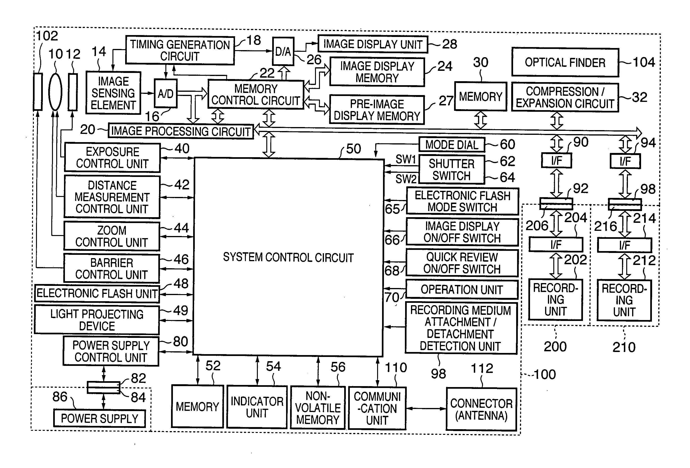
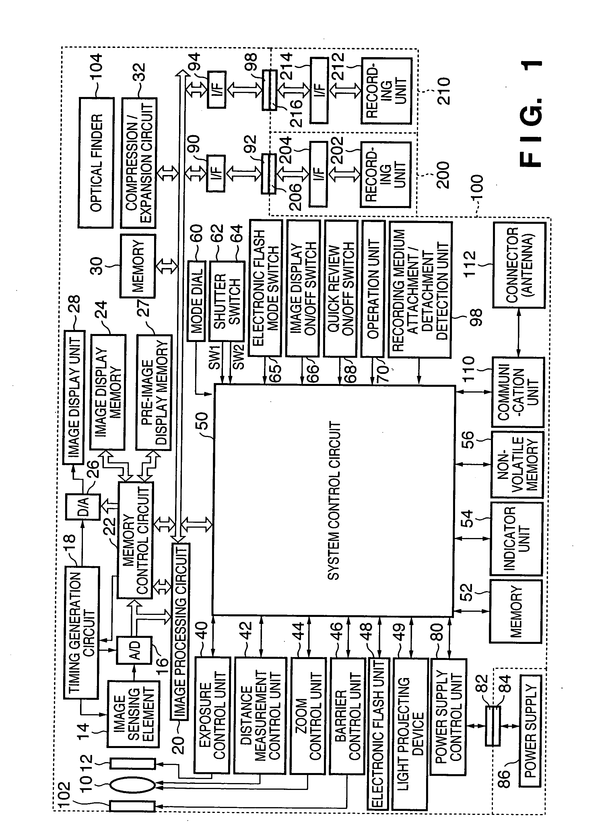
[0187]FIG. 13 is a block diagram of a digital camera apparatus according to the second embodiment. This arrangement is based on that shown in FIG. 1 (the arrangement of the first embodiment). Different components and characteristic features will be described below.

[0188] The arrangement of the second embodiment is different from that in FIG. 1 in that an image shift detection unit 29 is arranged. The image shift detection unit 29 detects the coordinate moving amount of an image and that of an object by photographer's camera shake from two images which continue in terms of time.

[0189]

[0190] The red-eye processing (step S123 in FIG. 3A) according to the first embodiment is executed in the order of processing operations shown in FIGS. 11A and 11B. Red-eye processing according to the second embodiment is executed in accordance with the flowcharts shown in FIGS. 12A and 12B. This will be described below with ...

third embodiment

[0211] The third embodiment will be described next. The apparatus arrangement according to the third embodiment is the same as that shown in FIG. 13. As a characteristic feature, the light emission mode in red-eye relaxation processing includes a red-eye relaxation effect priority mode (the same processing as in the first and second embodiments and will be referred to as red-eye relaxation mode 1 hereinafter) as the first mode and red-eye relaxation speed priority mode (a mode which simplifies red-eye relaxation processing and puts priority on the instruction from the shutter switch SW2 and will be referred to as red-eye relaxation mode 2 hereinafter) as the second mode. One of the two modes is selected by operating a switch provided on an operation unit 70.

[0212]

[0213] Red-eye processing (step S123 in FIG. 3A) according to the third embodiment will be described with reference to the flowcharts shown in FIGS. 15A and 15B.

[0214] A system control circuit 50 checks whether the electr...

fourth embodiment

[0231] The fourth embodiment will be described. The apparatus arrangement according to the fourth embodiment is the same as that shown in FIG. 13, and a description thereof will be omitted.

[0232] In the first to third embodiments, red-eye relaxation light projection is executed before flash photography. In the fourth embodiment, after flash photography, processing waits until a predetermined time elapses, and flash photography is executed again. The position of a red eye is detected from the comparison result between the two images.

[0233]

[0234] The processing procedures of the fourth embodiment will be described with reference to FIGS. 16 to 18A and 18B. FIGS. 16, 17A, and 17B show the main processing in the fourth embodiment. FIGS. 18A and 18B show details of photography processing in step S2132 in FIG. 16.

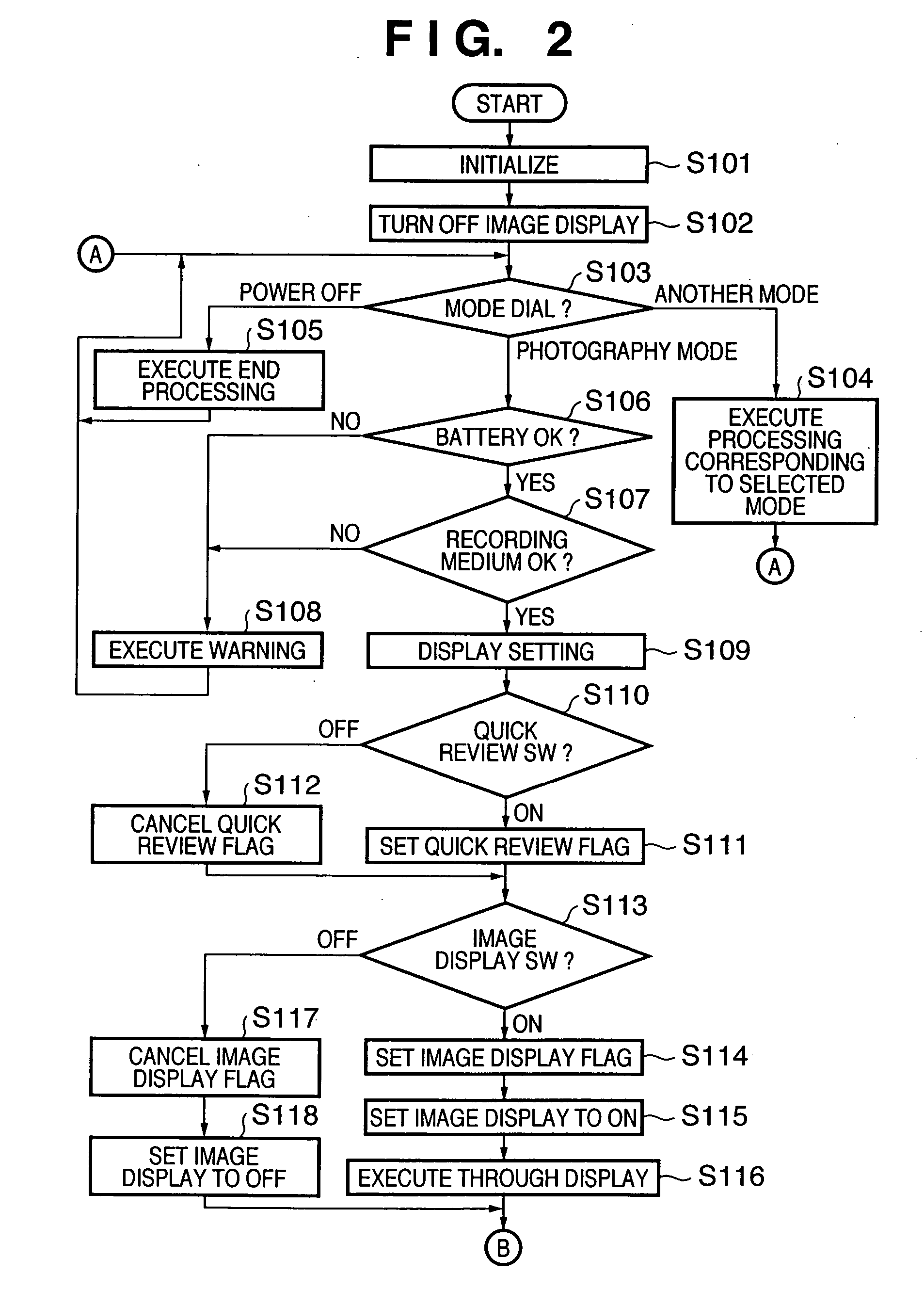
[0235] Referring to FIG. 16, when the apparatus is powered on by, e.g., loading a new battery, a system control circuit 50 initializes flags and control variables (step S2101)...


PUM


Abstract

This invention makes it possible to execute photography with a sufficient red-eye relaxation effect. To do this, in this invention, the amount of a red eye is detected on the basis of a signal obtained by reading an object image under light projection by a light projection unit. The light projection by the light projection unit is controlled on the basis of the detection result.

Description

CLAIM OF PRIORITY [0001] This application claims priorities from Japanese Patent Application Nos. 2003-274738 filed on Jul. 15, 2003 and 2003-435452 filed on Dec. 26, 2003 the entire contents of which are incorporated herein by reference. FIELD OF THE INVENTION [0002] The present invention relates to control and a program for relaxing a red-eye effect that occurs when an image sensing apparatus is used. BACKGROUND OF THE INVENTION [0003] To relax a red-eye effect in photography using an electronic flash (flash), a technique is conventionally used, in which human pupils are pre-illuminated with flash light before photography, thereby contracting the pupils (e.g., Japanese Patent Publication No. 58-48088). This technique should suppress the amount of flash light reflected by retinas by contracting the pupils before photography. [0004] In another technique used in a digital still camera, image data by flash photography and that by non-flash photography are compared. With this processin...

Claims


Application Information

Patent Timeline
IPC IPC(8): G06K9/00H04N5/225H04N1/62
CPCG06K9/0061H04N1/62H04N1/624G06V40/193H04N23/00
Inventor ICHIMASA, SHOJI
Owner CANON KK
Why Eureka
Try Eureka