Image forming apparatus, image forming method, and fixing unit

a technology of image forming and fixing unit, which is applied in the direction of electrographic process apparatus, instruments, optics, etc., can solve the problems of deteriorating convenience for users, increasing the importance of environmental problems, and longer waiting time, so as to minimize the turnaround time of image forming jobs

Inactive Publication Date: 2005-01-20
RICOH KK
View PDF2 Cites 32 Cited by
  • Summary
  • Abstract
  • Description
  • Claims
  • Application Information

AI Technical Summary

Benefits of technology

The image forming apparatus according to one aspect of the present invention includes a fixing unit that thermally fixes a toner image using a fixing member, where the fixing unit is heated by a heat generating member that generates heat by power supply from a chargeable auxiliary power supply; a power control unit that controls the power supply from the auxiliary power supply to the heat generating member based on a charging voltage of the auxiliary power supply; a job-turnaround-time predicting unit that predicts a job turnaround time required for executing an image forming job; a charging-time predicting unit that predicts a charging time for charging the auxiliary power supply to a predetermined charging voltage based on the charging voltage of the auxiliary power supply; and a control unit that controls a charging operation for the auxiliary power supply and execution of the image forming job based on the job turnaround time predicted and the charging time predicted, such that the job turnaround time for the image forming job is minimized.

Problems solved by technology

In recent years, environmental problems have increased in importance, and efforts have been made to reduce energy consumption in the image forming apparatus such as the copying machine or the printer.
However, in a conventional structure for the fixing unit, if power is reduced to zero when the fixing unit is on standby, it takes time to warm up a heating roller thereof when the fixing unit is used again.
This makes waiting time longer and deteriorates convenience for a user.
Therefore, the fact of the matter is that, even if it is attempted to warm up the heating roller in a short time, the upper limit of the input energy cannot be lifted.
However, since a thermal capacity of the heating roller decreases, in the case of an image forming apparatus with high print speed, temperature may fall if continuous printing is performed even in a state in which temperature on the surface of the heating roller has risen to a set temperature.
Such a secondary battery has a characteristic that a capacity thereof deteriorates and decreases when charge and discharge are repeated many times and a useful life thereof is reduced when discharge is performed with a larger current.
Therefore, the secondary battery has a disadvantage that time and labor are required for replacement of the battery, and running cost such as cost for the battery to be replaced increases.
Moreover, a lead-acid storage battery is not preferable as office equipment because, for example, the battery uses liquid sulfuric acid.
If a print operation is performed in a state in which sufficient power is not charged in the auxiliary power supply, charge in the auxiliary power supply is fully consumed in the midstream of the print operation.
As a result, print speed falls from the midstream of the print operation, and if power of the auxiliary power supply runs short, an image with a poor fixing property is obtained unless fall in temperature in the heating roller is prevented by taking measures such as increasing an interval of print operations.
However, in any event, longer time is required until completion of a print operation compared with a case in which a fully charged auxiliary power supply is used.

Method used


Image

  • Image forming apparatus, image forming method, and fixing unit
  • Image forming apparatus, image forming method, and fixing unit
  • Image forming apparatus, image forming method, and fixing unit

Examples


first embodiment

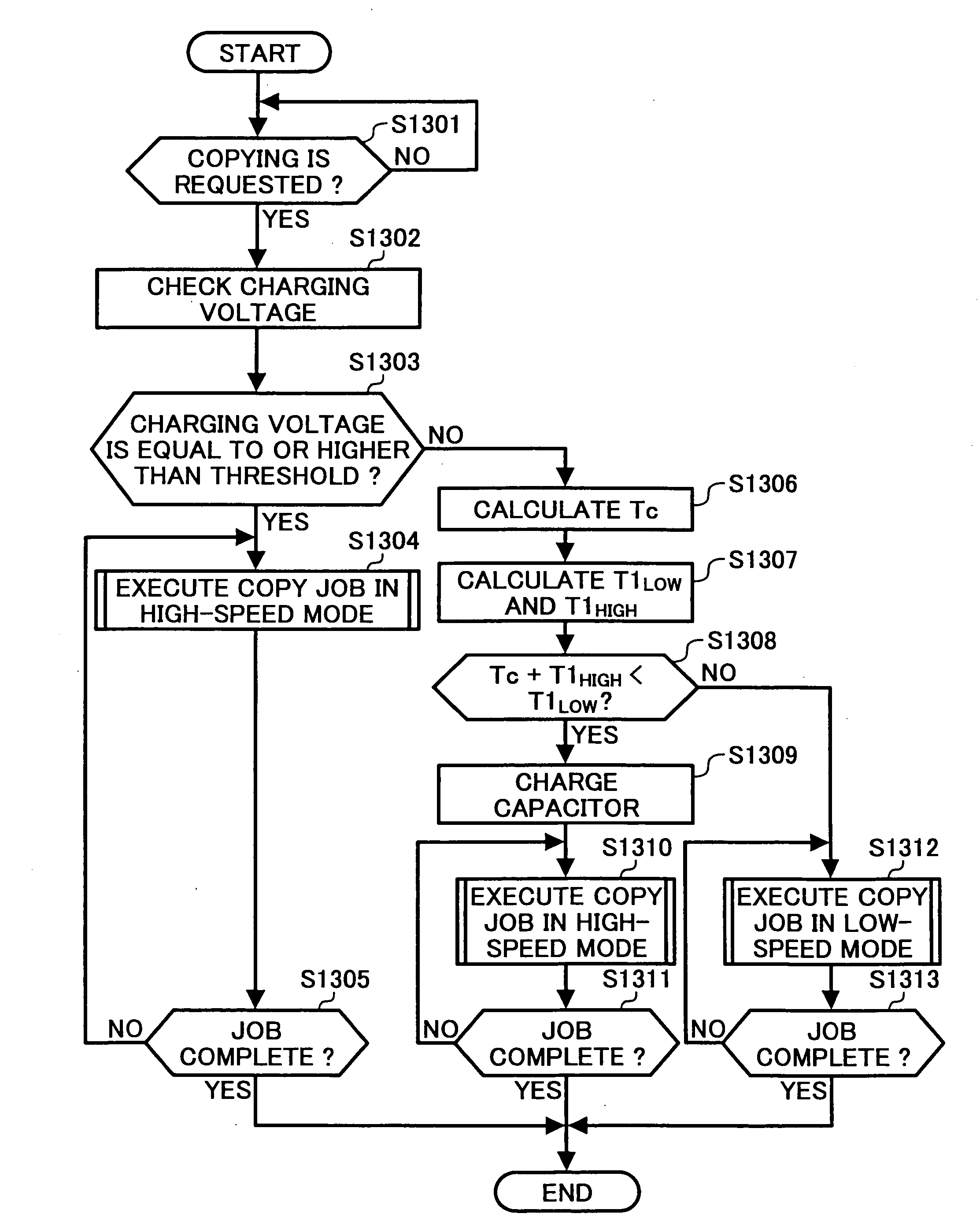
the control unit 202 calculates a charging time for charging the capacitor CP1 to a predetermined charging voltage and also calculates a turnaround time of a set copy job, and then controls execution of a charging operation for the capacitor CP1 and execution of the copy job based on the calculated charging time and the calculated turnaround time of the copy job such that the turnaround time of the copy job is minimized. Thus, when the capacitor CP1 is used as a power supply source for a fixing unit, even in a state in which the capacitor CP1 is not charged sufficiently, a completion time for the copy job can be minimized under the constraints.

Furthermore, according to the first embodiment, the image forming apparatus has the high-speed mode and the low-speed mode, and the control unit 202 calculates a turnaround time of a copy job set for each of the modes, executes the copy job in the high-speed mode after charging the capacitor CP1 when a sum of a charging time and the turnaroun...

second embodiment

Therefore, in the image forming apparatus according to the present invention, a job completing time is further minimized by, when a voltage at the capacitor CP1 has decreased to a threshold voltage while the job is executed in the high-speed mode, switching the high-speed mode to the low-speed mode.

A structure of the image forming apparatus according to the second embodiment is the same as that in the first embodiment.

FIG. 16 is a flowchart of a process procedure for a copy job in the control unit 202 of an image forming apparatus according to the second embodiment. The control for the copy job in the control unit 202 will be explained with reference to FIG. 16. When the operation unit 150 requests copying (step S1601), the control unit 202 checks a charging voltage at the capacitor CP1 (step S1602) and judges whether the charging voltage is equal to or higher than a threshold charging voltage decided in advance (e.g., 32 volts) (step S1603).

Processing at the time when the charg...

third embodiment

Therefore, in the image forming apparatus according to the present invention, a job completing time is further minimized by, when the control unit 202 executes a job in the high-speed mode after charging the capacitor CP1, predicting a job completing time at the time when a charging voltage at the capacitor CP1 falls to the threshold charging voltage during execution of the job and the control unit 202 switches the high-speed mode to the low-speed mode to execute the job.

A structure of the image forming apparatus according to the third embodiment is the same as that in the first embodiment.

FIG. 18 is a flowchart of a process procedure for a copy job in the control unit 202 of an image forming apparatus according to the third embodiment. The control for the copy job in the control unit 202 will be explained with reference to FIG. 18. When the operation unit 150 requests copying (step S1801), the control unit 202 checks a charging voltage at the capacitor CP1 (step S1802) and judges...


PUM


Abstract

An image forming apparatus includes a fixing unit that thermally fixes a toner image, a power control unit that controls a power supply from an auxiliary power supply to the fixing unit, a job-turnaround-time predicting unit that predicts a job turnaround time for executing an image forming job, a charging-time predicting unit that predicts a charging time for charging the auxiliary power supply, and a control unit that controls a charging operation for the auxiliary power supply and execution of the image forming job based on the job turnaround time predicted and the charging time predicted, such that the job turnaround time for the image forming job is minimized.

Description

CROSS-REFERENCE TO RELATED APPLICATIONS The present document incorporates by reference the entire contents of Japanese priority documents, 2003-161331 filed in Japan on Jun. 5, 2003 and 2004-161777 filed in Japan on May 31, 2004. BACKGROUND OF THE INVENTION 1) Field of the Invention The present invention relates to an image forming apparatus, an image forming method, and a fixing unit, and more particularly, to an image forming apparatus like a copying machine, a digital multifunction product, and a printer that apply heat to a fixing member of a fixing unit using an auxiliary power supply, an image forming method, and a fixing unit that is used in the image forming apparatus. 2) Description of the Related Art The image forming apparatus such as the copying machine or the printer forms an image on a recording medium like plain paper or an OHP transparency. In this image formation, an electrophotographic system is adopted taking into account high speed of the image formation, an...

Claims


Application Information

Patent Timeline
Patent Type & Authority Applications(United States)
IPC IPC(8): G03G15/00G03G15/20G03G21/00
CPCG03G15/2039
Inventor SATOH, NAOKITAKAMATSU, RYOISHIZAKI, YUUSUKE
Owner RICOH KK
Why Eureka
Try Eureka