Impeller and sewage treatment pump including the same

Active Publication Date: 2005-01-20
SHIN MEIWA IND CO LTD
View PDF11 Cites 9 Cited by
  • Summary
  • Abstract
  • Description
  • Claims
  • Application Information

AI Technical Summary

Benefits of technology

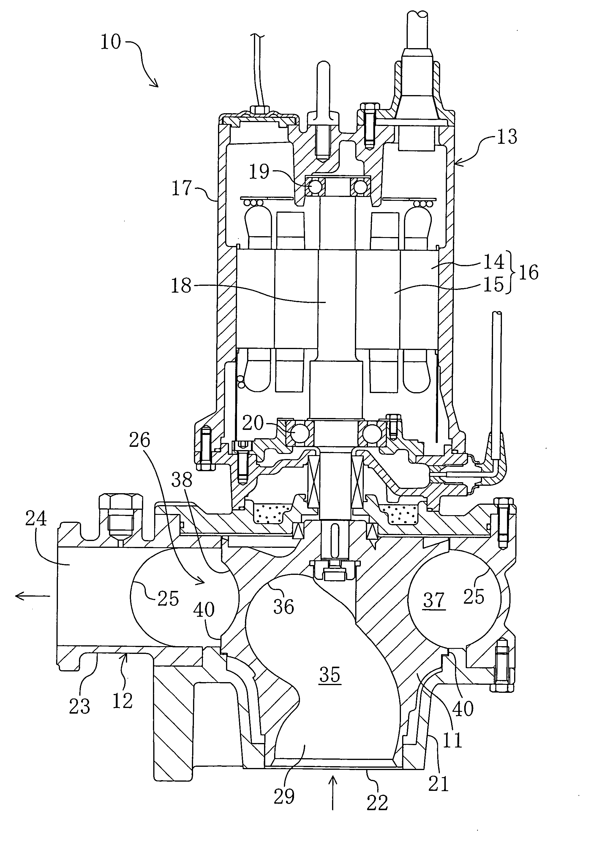
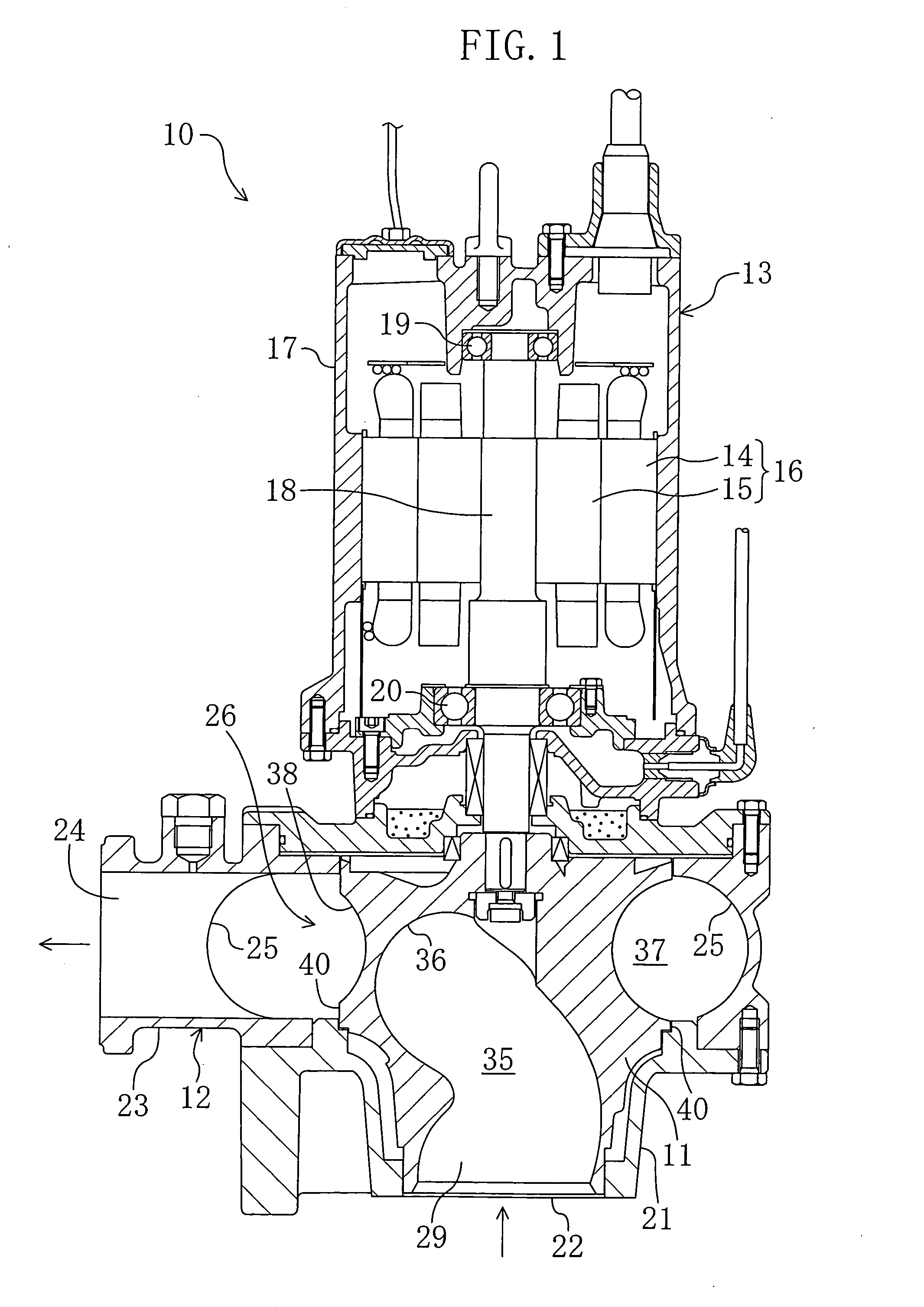
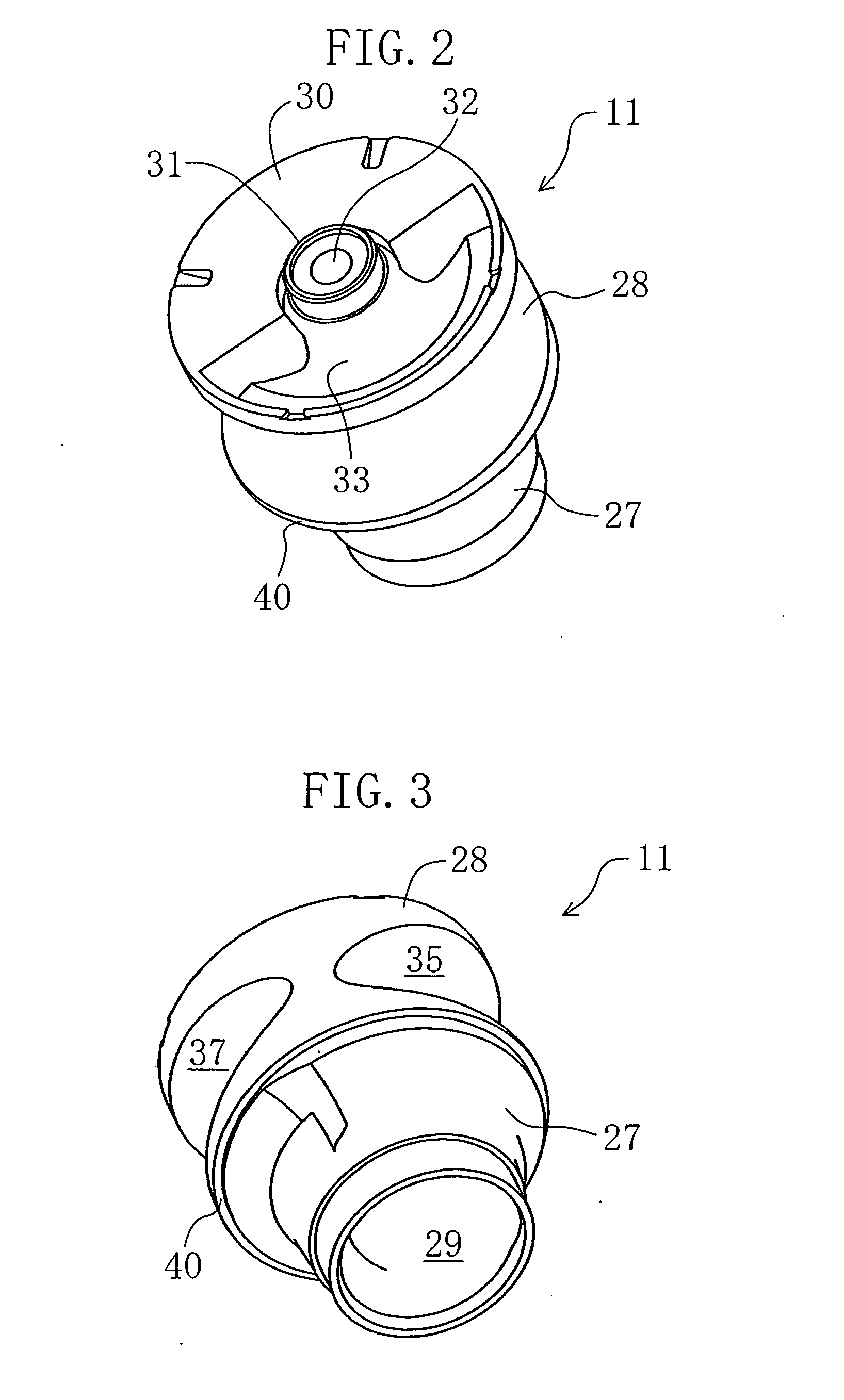
[0010] The above impeller is of so-called closed type in which the inlet side and the outlet side are partitioned by the flange portion. Therefore, contaminants are less involved and choking occurs less inside the impeller. Since the channel (primary channel) from the inlet to the outlet is formed spirally, a sewage stagnating region inside the impeller is minimized and contaminants smoothly flow through the spiral channel. Hence, contaminants is hard to be choked inside the impeller.
[0011] The secondary vane is provided in the above impeller, so that the secondary channel is formed which is connected to the spiral channel and formed around the outer periphery. With this configuration, sewage sucked from the inlet is conveyed by both the primary vane and the secondary vane. As a result, the discharge pressure becomes high and the pumping efficiency is increased.
[0012] Hence, the above impeller attains both excellent foreign matter passability and increase in pumping efficiency.
[0013] In addition, since the secondary vane is formed in a shape that a part of the outer periphery of the impeller is gouged inward, weight reduction is attained compared with impellers having no secondary vane.
[0014] Preferably, the secondary vane extends over a length equal to or longer than one half of the circumference of the impeller. With this arrangement, the pumping efficiency is further increased.

Problems solved by technology

In pumps for treating sewage with which foreign matter such as contaminants is mixed, involvement of such foreign matter and choking inside the impellers are liable to be caused, especially in low flow rate regions.

Method used


Image

  • Impeller and sewage treatment pump including the same
  • Impeller and sewage treatment pump including the same
  • Impeller and sewage treatment pump including the same

Examples


modified examples

[0076] The impeller and the pump according to the present invention are not limited to the above embodiment and includes various modified examples.

[0077] The shapes in channel section of the primary channel 35 and the secondary channel 37 are not limited to those in the above embodiment. In the above embodiment, the secondary vane 38 has the half circle channel section (FIG. 13), and may have a semi-ellipse channel section or a substantially rectangular shaped channel section (FIG. 26), for examples. No limitation is imposed on the shape in channel section of the secondary vane 38.

[0078] The above embodiment uses an impeller of so-called radial flow type in which sewage is discharged in the direction intersecting at a right angle with the axial direction. However, the impeller according to the present invention is not limited to only the radial flow type and may be an impeller of so-called diagonal flow type (or mixed flow type) in which sewage is discharged diagonally upward.

[00...


PUM


Abstract

In an impeller 11, an inlet portion and an outlet portion are provided at one end side and the other end side in the axial direction, respectively. An inlet 29 is formed in the lower part of the inlet portion, and an outlet is formed in the side face of the outlet portion. The inlet portion and the outlet portion are partitioned by a flange portion 40. The impeller 11 includes a primary vane 36 and a secondary vane 38. The primary vane 36 defines a spiral primary channel 35 that connects the inlet 29 and the outlet. The secondary vane 38 is formed in a shape that a part of the outer periphery of the outlet portion is gouged inward so as to define a secondary channel 37 connected to the primary channel 35 and extending circumferentially around the outer periphery.

Description

CROSS REFERENCE TO RELATED APPLICATIONS [0001] This Non-provisional application claims priority under 35 U.S.C. §119(a) on patent application Ser. No. 2003-277163 filed in Japan on Jul. 18, 2003, the entire contents of which are hereby incorporated by reference. BACKGROUND OF THE INVENTION [0002] 1. Field of the Invention [0003] The present invention relates to impellers and sewage treatment pumps including the same. [0004] 2. Description of the Prior Art [0005] As impellers of sewage treatment pumps, impellers of vortex type, non-clogging type and screw type have been used dominantly. Additionally, an impeller in which a spiral channel is formed inside has been known (see Japanese Patent Publication No. 28-5840B). [0006] In pumps for treating sewage with which foreign matter such as contaminants is mixed, involvement of such foreign matter and choking inside the impellers are liable to be caused, especially in low flow rate regions. SUMMARY OF THE INVENTION [0007] The present inven...

Claims


Application Information

Patent Timeline
IPC IPC(8): F04D1/04F04D7/04F04D29/22F04D29/24
CPCF04D29/2288
Inventor NISHI, YASUYUKITAKEBE, CHIKARATAMURA, KOICHITAMAKI, YOICHIANDO, AKIHIROFUNASAKA, ARATA
Owner SHIN MEIWA IND CO LTD
Why Eureka
Try Eureka