Rotor blade tip section

Active Publication Date: 2005-01-20
SIKORSKY AIRCRAFT CORP
View PDF7 Cites 46 Cited by
  • Summary
  • Abstract
  • Description
  • Claims
  • Application Information

AI Technical Summary

Benefits of technology

[0006] The main rotor blade according to the present invention provides a non-straight tip section, which includes a splice cap, a tip spar, a core and an upper and lower non-structural tip skin. The core and skins need not be structural members as the tip spar carries rotor blade tip section torsional loads. Relatively complex tip section forms that utilize a minimum of structural components are readily achieved by the present invention.
[0007] The tip section is mounted to a central blade section by mounting the tip spar to a main blade spar. The tip spar includes a first surface substantially parallel to a second surface. The first and second surfaces

Problems solved by technology

The tip section of the main rotor blade is subjected to the greatest stresses/strains due to aerodynamic forces, and concomitantly experiences the greatest structural degradation due to wear and abrasion (due to the high rotational velocity of the main rotor blade tip), during operation of the helicopter main rotor assembly.
Disadvantageousl

Method used


Image

  • Rotor blade tip section
  • Rotor blade tip section
  • Rotor blade tip section

Examples


Embodiment Construction

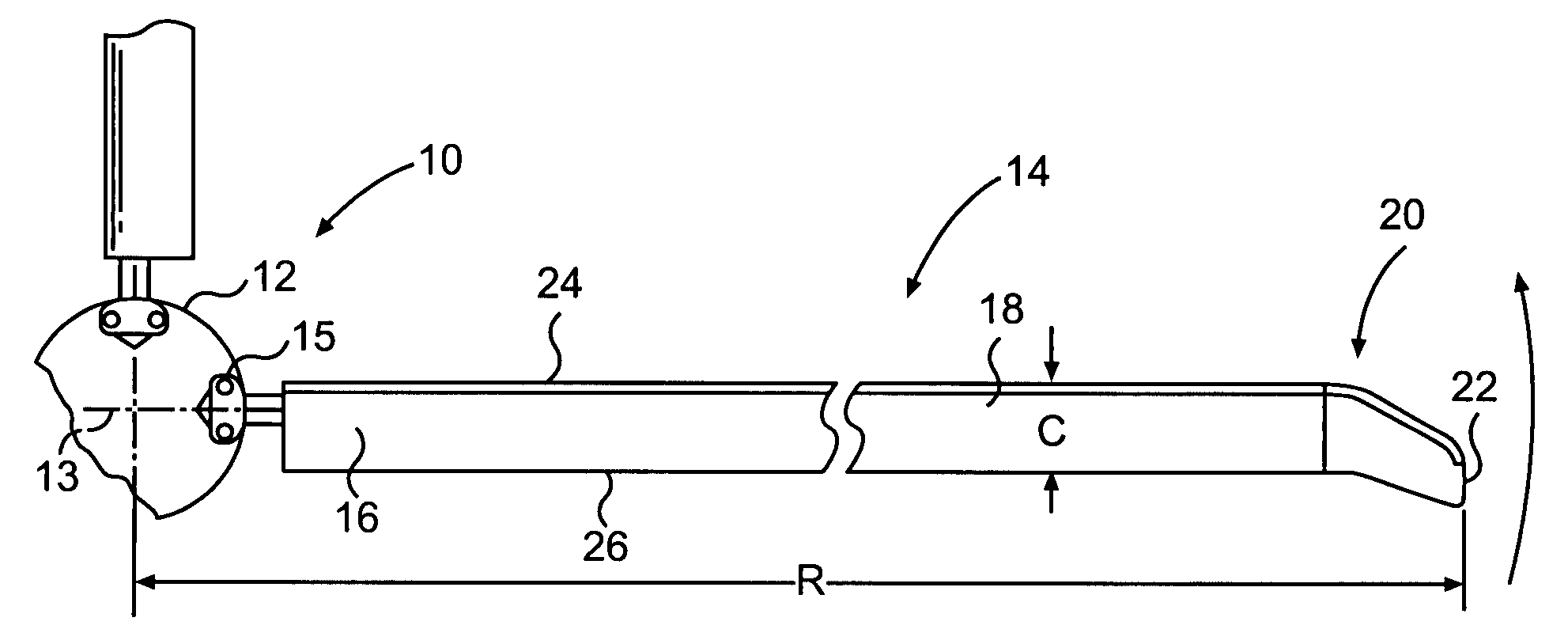
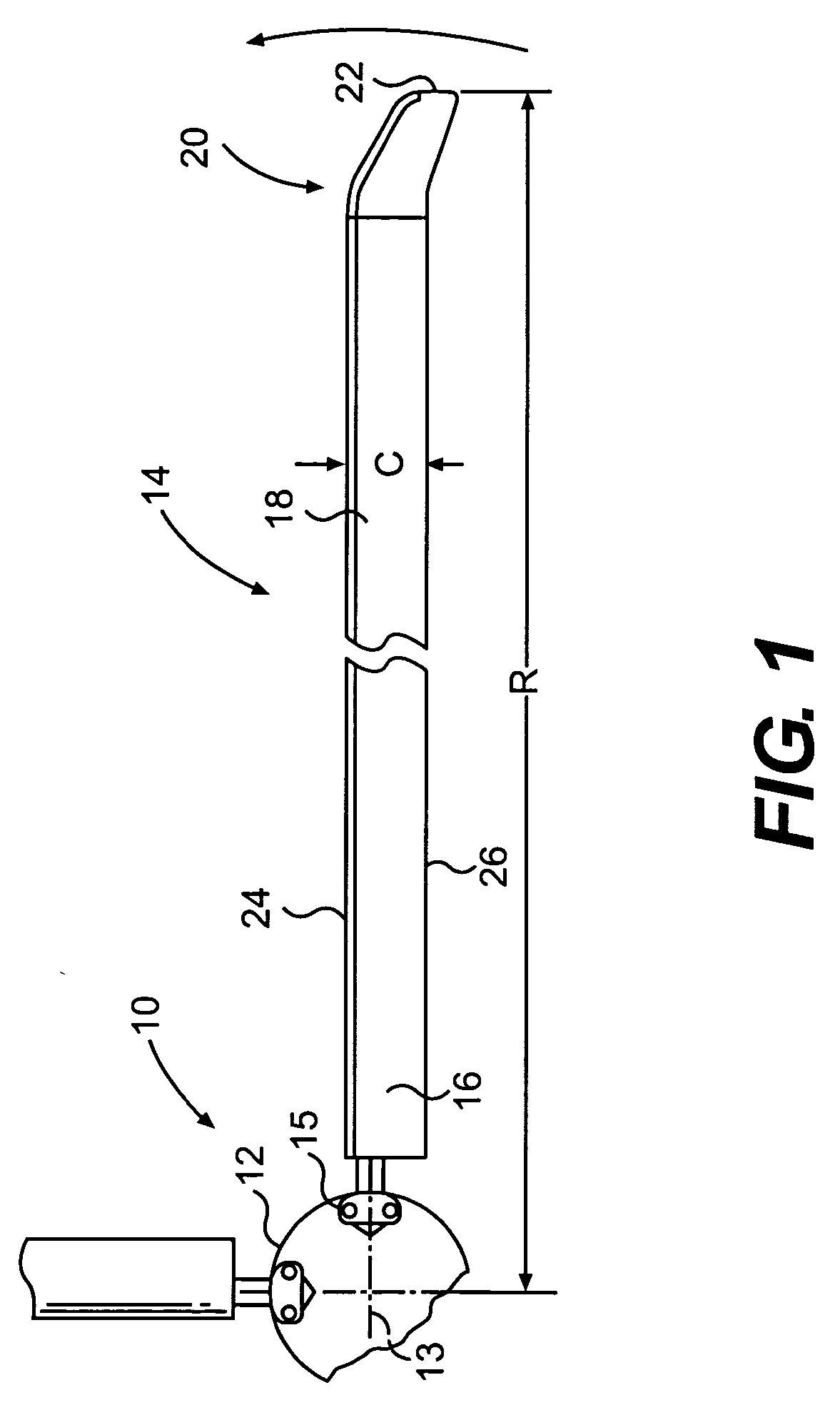
[0017]FIG. 1 illustrates a general perspective view of a helicopter rotor system 10 which includes a hub assembly 12 to be driven for rotation about an axis of rotation 13. A plurality of main rotor blade assemblies 14 project substantially radially outward from the hub 12 and are supported therefrom in conventional fashion by an attachment 15. Any number of blades 14 may be used with the rotor system 10. It should be understood that although a particular rotor system 10 is illustrated in the disclosed embodiment, other attachments, flex beams, main and tail rotors will benefit from the present invention.

[0018] Each main rotor blade 14 includes a root section 16, a central section 18 of aerodynamic shape, and a tip section 20, which culminates in a blade tip 22. The blade sections 16, 18, 20 cooperate with the hub 12 to define a blade radius R between the axis of rotation 13 and the blade tip 22. A blade chord C extends between a blade leading edge 24 and a blade trailing edge 26. ...


PUM


Abstract

A main rotor blade includes a tip section having a splice cap, a structural tip spar, a core and an upper and lower tip skin. The tip section is mounted to a central blade section by mounting the tip spar to a main blade spar. The tip spar includes a first surface substantially parallel to a second surface. The first and second surfaces each extend from a shear web therebetween to define the generally C-shape in cross section. The shear web generally carries rotor blade torsional loads and eliminates the heretofore required structural core. A section of the tip spar overlaps a section of the main blade spar. The tip section thereby transfers the loads carried thereby through interaction between the overlapped spar sections. The tip section core and skins need not be structural members as the tip spar carries rotor blade tip section torsional loads.

Description

BACKGROUND OF THE INVENTION [0001] The present invention relates to a rotary wing aircraft rotor blade, and more particularly to a rotor blade tip spar arrangement. [0002] Conventional rotary wing aircraft rotor blades often include a tip section of a selected sweep, taper, and form to improve the blade performance. Anhedral tip sections increase hover performance and lift capabilities of a rotary wing aircraft on which the blades are fitted without increasing the structural features of the main rotor hub and spindle. [0003] The tip section of the main rotor blade is subjected to the greatest stresses / strains due to aerodynamic forces, and concomitantly experiences the greatest structural degradation due to wear and abrasion (due to the high rotational velocity of the main rotor blade tip), during operation of the helicopter main rotor assembly. These forces are only increased upon a tip section which utilizes an anhedral or other non-straight form. [0004] Disadvantageously, a tip s...

Claims


Application Information

Patent Timeline
IPC IPC(8): B64C27/46
CPCB64C27/46B64C2027/4736B64C27/463
Inventor KOVALSKY, DAVID A.JONES, COREY D.VIOLA, KEVIN P.
Owner SIKORSKY AIRCRAFT CORP
Why Eureka
Try Eureka