Cooling air inlet arrangement

a technology of cooling air and inlet arrangement, which is applied in the direction of positive displacement liquid engines, piston pumps, liquid fuel engines, etc., can solve the problems of allowing noise to leave the compressor housing, and achieve the effect of reducing the amount of noise emitted by the machine and reducing the nois

Inactive Publication Date: 2005-01-20
DOOSAN INT USA
View PDF9 Cites 13 Cited by
  • Summary
  • Abstract
  • Description
  • Claims
  • Application Information

AI Technical Summary

Benefits of technology

[0006] The present invention utilizes a two fan design with one fan in the rearward portion of the compressor housing, and a second fan in the forward portion of the housing. The housing preferably has rear louvers near the back of the housing and mid louvers near the intermediate section of the housing. These louvers have noise reducing baffles and are strategically located in the housing to accommodate the needs for cool air and directing the air to specific parts, while reducing the amount of noise emitted by the machine. The invention locates cool air inlets in certain locations to direct cool air across critical components. Cool ambient air is drawn through baffled louvers primarily by a hydraulic powered rear fan, and secondarily by the front fan.

Problems solved by technology

However, inlets that allow ambient air to enter the compressor housing also allow noise to leave the compressor housing.
There is a trade off between cooling air and compressor noise, and manufacturer's must consider Environmental Protection Agency (EPA) and European Community (EC) noise requirements when designing air compressor units.

Method used


Image

  • Cooling air inlet arrangement
  • Cooling air inlet arrangement
  • Cooling air inlet arrangement

Examples


Embodiment Construction

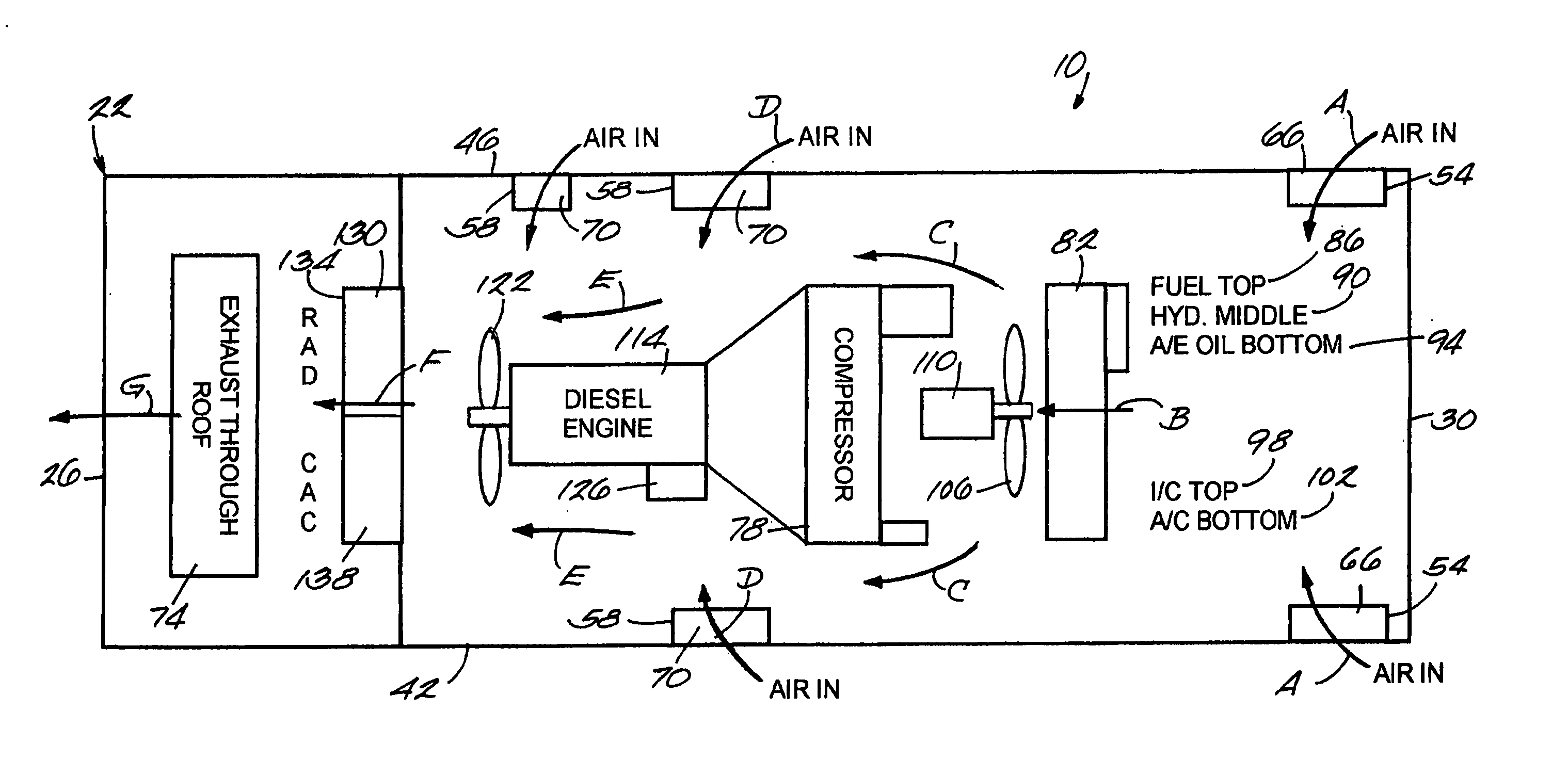
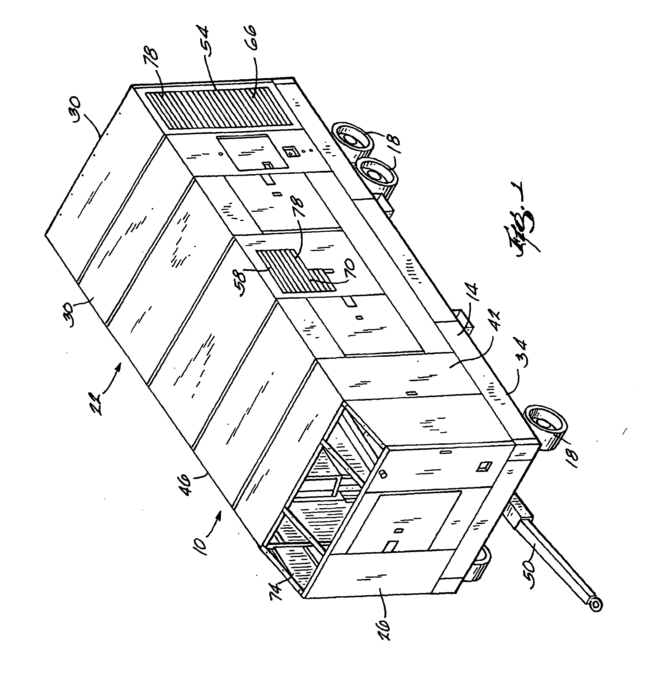
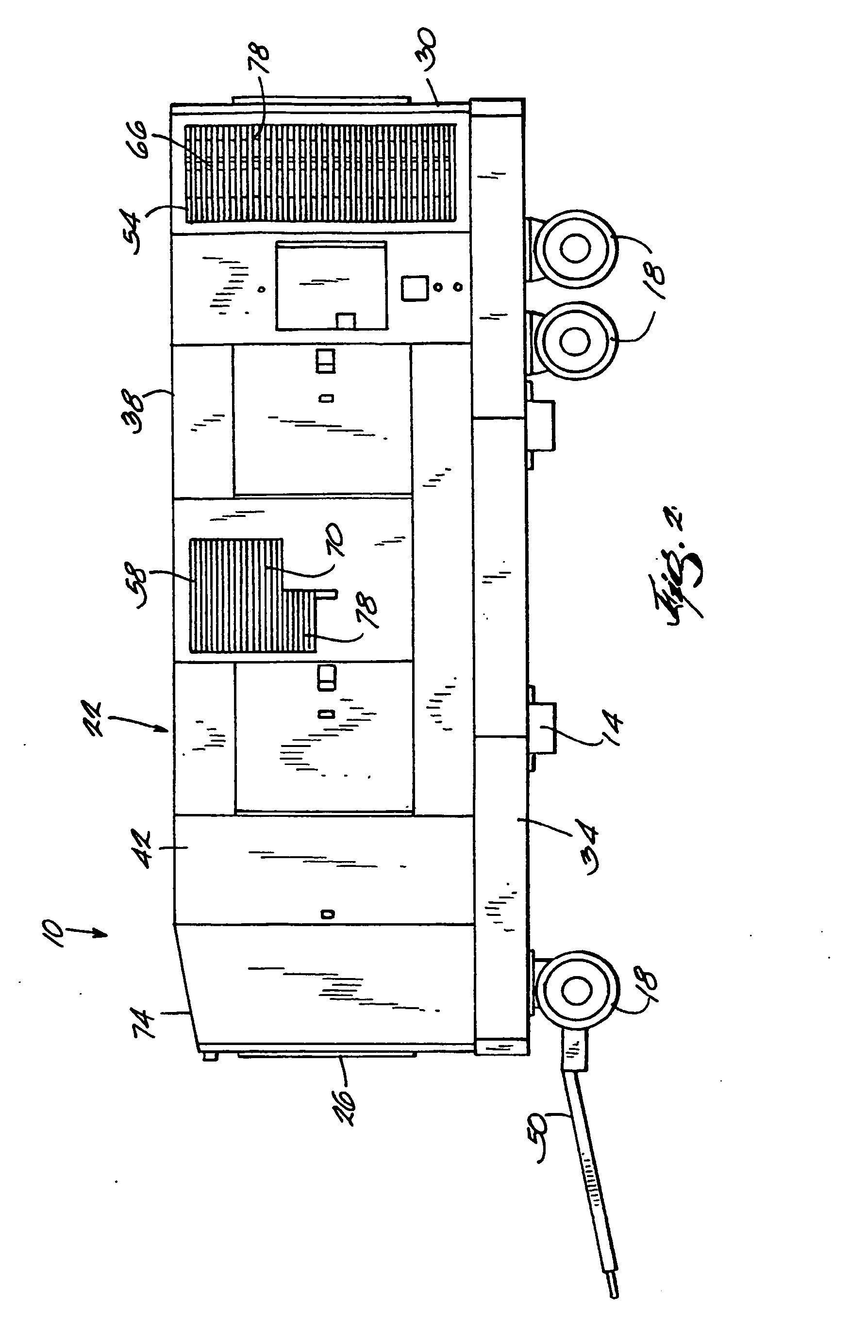
[0014]FIG. 1 illustrates a portable air compressor unit 10 that compresses air to pressures above normal atmospheric pressures. The compressor unit 10 includes a frame 14, wheels 18 supporting the frame 14, and a housing 22 supported by the frame 14. The housing 22 has a front end 26 and a rear end 30 disposed at opposite ends of the housing 22. The housing 22 includes a base 34, a roof 38, a left portion 42, and a right portion 46 that extend between the front end 26 and the rear end 30. The compressor unit 10 also has a tongue 50 that may interconnect to a vehicle and facilitate transporting the portable air compressor unit 10.

[0015] The frame 14 supports the housing 22 and the internal components of the air compressor unit 10 disposed within the housing 22. In the illustrated embodiment, the housing 22 is a substantially rectangular box, but the housing may be any shape that substantially encloses the components of the compressor unit 10. The internal components of the air compr...


PUM


Abstract

A portable air compressor unit (10) having a housing (22) with a rear end (30) and front end (26). The housing (22) includes a rear louver (66) near the rear end (30), an exhaust outlet (74) near the front end (26) and a mid louver (70) between the rear and front end. A rear cooler set (82) and rear fan (106) are disposed within the housing between the rear louver and mid louver. The fan (106) draws cooling air into the housing through rear louver (66) and through the rear cooler set (82). A front fan (122) and front cooler set (130) are disposed within the housing (22) between the mid louver (70) and exhaust outlet (74).

Description

[0001] This Patent Application claims the benefit of the earlier filing date of provisional patent application No. 60 / 259,989 filed Jan. 5, 2001.FIELD OF THE INVENTION [0002] This invention relates to air compressors, and more particularly to cooling systems for air compressors. BACKGROUND OF THE INVENTION [0003] To ensure the reliability of an air compressor in all environments, it is critical that an adequate supply of cool ambient air is properly routed through the compressor assembly and into key areas of the compressor. The operating requirements of the compressor and the engine are directly related to how well heat exchangers transfer heat from the compressor components to the ambient air. The unit design and layout must ensure that a sufficient amount of cool ambient air is available for all the heat exchangers, batteries, instrument panels, electronic controls, intakes to the compressor and engine, and other components. However, inlets that allow ambient air to enter the com...

Claims


Application Information

Patent Timeline
Patent Type & Authority Applications(United States)
IPC IPC(8): F01C21/00F01P3/18F01P3/20F01P5/02F01P11/12F02B63/06F04B35/00F04B35/06F04B39/00F04C23/00F04C29/04
CPCF01C21/007F01P3/18F01P3/20F01P5/02F01P11/12Y02T10/17F04B35/002F04B35/06F04B39/0033F04C23/00F04C29/04F02B63/06Y02T10/12
Inventor DYSON, MICHAEL SHANEHANCOCK, MARION DANIEL IIHENDRIX, DEAN P.STAHLMAN, DAVID B.WOOD, DONALD M.
Owner DOOSAN INT USA
Why Eureka
Try Eureka