Systems and methods for providing a dynamically adjustable reciprocating fluid dispenser

a reciprocating fluid and fluid dispenser technology, applied in the direction of piston pumps, laboratory glassware, instruments, etc., can solve the problems of inability to readily calibrate the angular displacement of the port, the pump stroke is not easily adjusted, and the pump does not provide accurate calibration for metering and dispensing fluids. achieve the effect of dynamic, repeatable and extremely accurate fluid volum

Active Publication Date: 2005-01-20
ZAXIS
View PDF5 Cites 33 Cited by
  • Summary
  • Abstract
  • Description
  • Claims
  • Application Information

AI Technical Summary

Benefits of technology

[0013] Further implementation includes a controller coupled to the adjustment motor to dynamically control the adjustment motor to cause the adjustment mechanism to be precisely and repeatably modified. As such, the volume of fluid dispensed is extremely accurate, repeatable, and dynamic. Moreover, a controller may be used to provide control over the particular waveform of a synchronously and / or asynchronously reciprocating fluid dispenser.

Problems solved by technology

While the pump disclosed in U.S. Pat. No. 4,008,003 is an available technique, the pump does not provide an accurate calibration for metering and dispensing fluids.
For example, the piston stroke of the pump is not easily adjusted and the angular displacement of the ports cannot be readily calibrated.
Further problems with techniques used in industries that require a safe, accurate handling of fluid include the fact that complex pump designs increase the likelihood for error in manufacturing and assembling the pumps.
And, pump designs with moving parts contribute to field failure and maintenance costs.
Thus, while techniques currently exist that are used in industries requiring a safe, accurate handling of fluid, challenges still exist with such techniques, including a requirement for calibration of the fluid-handling device for each surrounding condition, an inability to provide accurate calibration, an increased likelihood for error, an increased likelihood for field failure, increased maintenance costs, and other such challenges.

Method used


Image

  • Systems and methods for providing a dynamically adjustable reciprocating fluid dispenser
  • Systems and methods for providing a dynamically adjustable reciprocating fluid dispenser
  • Systems and methods for providing a dynamically adjustable reciprocating fluid dispenser

Examples


Embodiment Construction

[0032] The present invention relates to accurately and repeatably dispensing fluid. In particular, the present invention relates to systems and methods for providing a dynamically adjustable, synchronously and / or asynchronously reciprocating fluid dispenser.

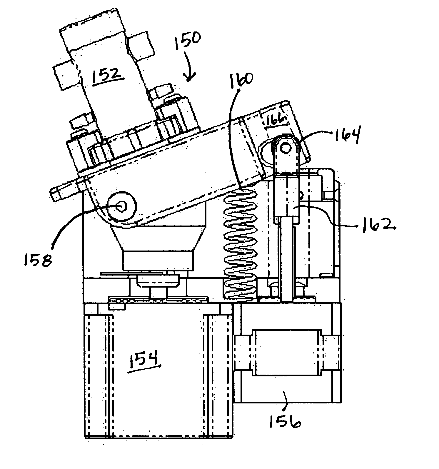
[0033] Embodiments of the present invention take place in association with a reciprocating fluid pump. In at least one embodiment, a pump drive motor is coupled to the reciprocating fluid pump to actuate a pump shaft within a pump cylinder, wherein the pump shaft includes a duct that allows fluid to selectively pass thereby within the pump cylinder. As the pump shaft rotates within the pump cylinder, fluid is allowed to enter into a pump bore defined by a portion of the pump cylinder through a pump ingress port. As the pump shaft rotates further, the shaft blocks the pump ingress port. Further rotation allows the duct of the shaft to allow the fluid in the pump bore to be dispensed through a pump egress port. This process may be...


PUM

PropertyMeasurementUnit
volumeaaaaaaaaaa
electricalaaaaaaaaaa
rotationaaaaaaaaaa

Abstract

Systems and methods for providing a dynamically adjustable, synchronously and/or asynchronously reciprocating fluid dispenser. A pump drive motor is coupled to the reciprocating fluid pump to actuate a pump shaft within a pump cylinder, wherein the pump shaft includes a duct that allows fluid to selectively pass thereby within the pump cylinder. As the pump shaft rotates within the pump cylinder, fluid is allowed to enter into a pump bore defined by a portion of the pump cylinder through a pump ingress port. As the pump shaft rotates, it blocks the pump ingress port. Further rotation allows the duct to allow the fluid in the pump bore to be dispensed through a pump egress port. An adjustment motor is coupled to an adjustment mechanism, which selectively adjusts the volume of the pump bore. A controller is coupled to the adjustment motor to dynamically control the adjustment motor, to cause the adjustment mechanism to be precisely and repeatably modified, and/or to control the particular waveform. As such, the volume of fluid dispensed is extremely accurate, repeatable, and dynamic.

Description

RELATED APPLICATIONS [0001] This application claims priority to U.S. Provisional Patent Application Ser. No. 60 / 472,190 filed May 20, 2003, entitled SYSTEMS AND METHODS FOR PROVIDING A DYNAMICALLY ADJUSTABLE RECIPROCATING FLUID DISPENSERBACKGROUND OF THE INVENTION [0002] 1. Field of the Invention [0003] The present invention relates to accurately and repeatably dispensing fluid. In particular, the present invention relates to systems and methods for providing a dynamically adjustable, synchronously and / or asynchronously reciprocating fluid dispenser. [0004] 2. Background and Related Art [0005] A variety of industries require a safe, accurate handling of fluid. One such industry is the medical industry. By way of example, in the medical industry an assay testing procedure is typically employed to determine whether an infectious disease (e.g., hepatitis or another infectious disease) is present in a particular blood serum. As part of the testing procedure, a biological sample is dispo...

Claims


Application Information

Patent Timeline
Patent Type & Authority Applications(United States)
IPC IPC(8): B01L3/02F04B7/06F04B9/02F04B49/12G01F11/02G01F11/20G01F11/22G01N1/00
CPCB01L3/0206B01L2200/143F04B7/06F04B9/02F04B49/12Y10T74/2107G01F11/029G01F11/20G01F11/22G01N35/1095G01N2030/326G01F11/023
Inventor PEELER, SCOTT C.GUEST, BRIAN W.
Owner ZAXIS
Why Eureka
Try Eureka