Method for locating the mechanical axis of a femur

a technology of mechanical axis and femoral head, which is applied in the field of computer assisted surgery, can solve the problems of introducing further errors into measurement, affecting the quality of readings, etc., and achieves the effect of improving accuracy and overcoming the influence of tracking nois

Active Publication Date: 2005-01-20
ORTHOSOFT ULC
View PDF1 Cites 208 Cited by
  • Summary
  • Abstract
  • Description
  • Claims
  • Application Information

AI Technical Summary

Benefits of technology

[0007] Accordingly, an object of the present invention is to overcome the influence of noise fo

Problems solved by technology

However, this technique is vulnerable to noise, thereby affecting the quality of the readings by the position sensing system.
Furthermore, th

Method used


Image

  • Method for locating the mechanical axis of a femur
  • Method for locating the mechanical axis of a femur
  • Method for locating the mechanical axis of a femur

Examples


Embodiment Construction

[0017] In a preferred embodiment of the invention, a Polaris™ optical camera is used with a Navitrack™ system sold by Orthosoft, Inc. A femoral tracker is optimally placed at an anterior position with respect to the sagittal anatomical axis and a lateral position with respect to the frontal anatomical axis. Ideally, the anterior position should be about 45 degrees and the lateral position should be about 10 degrees. The position to optimize accuracy for the bone trackers is about 12 cm from the knee joint facing the camera.

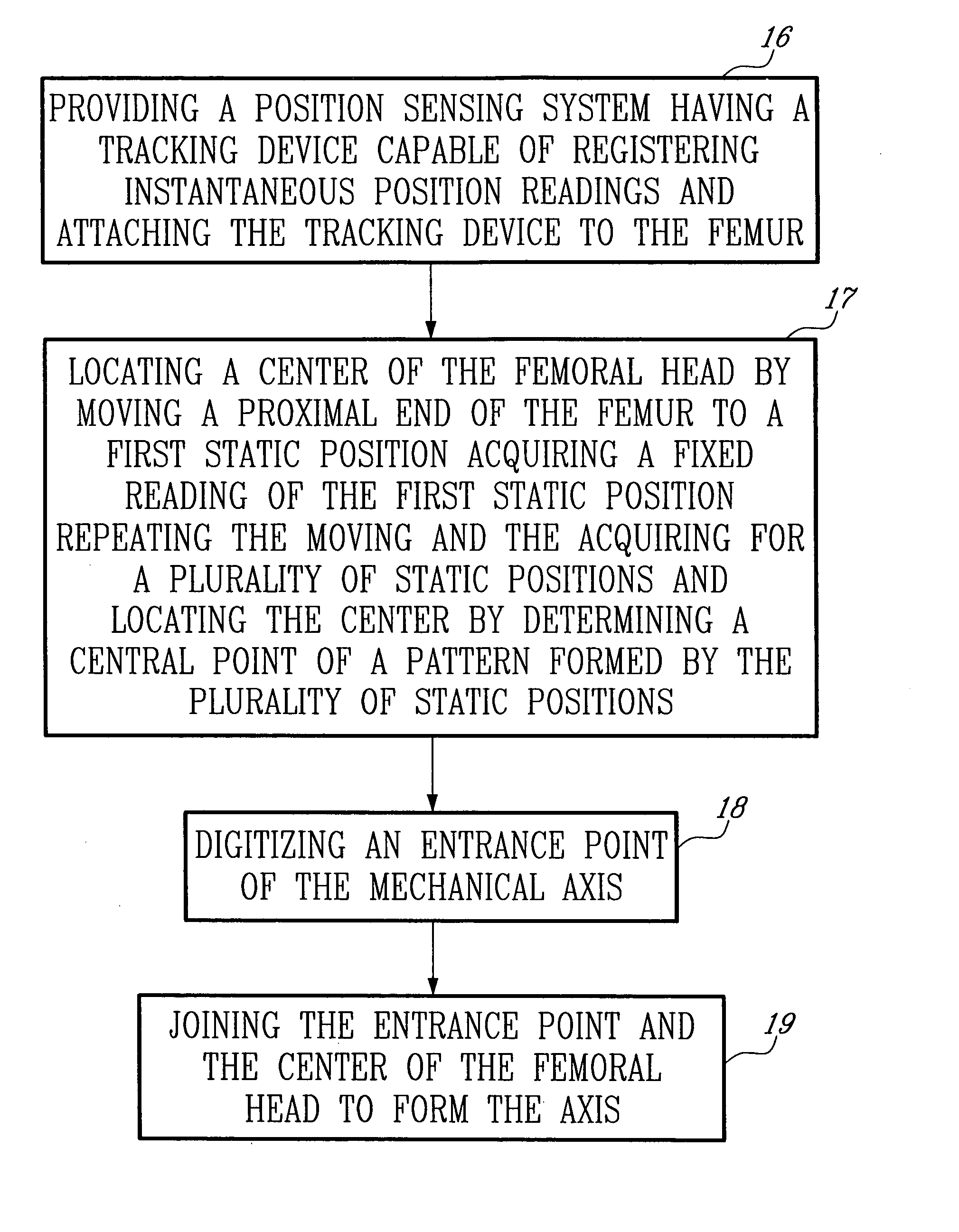
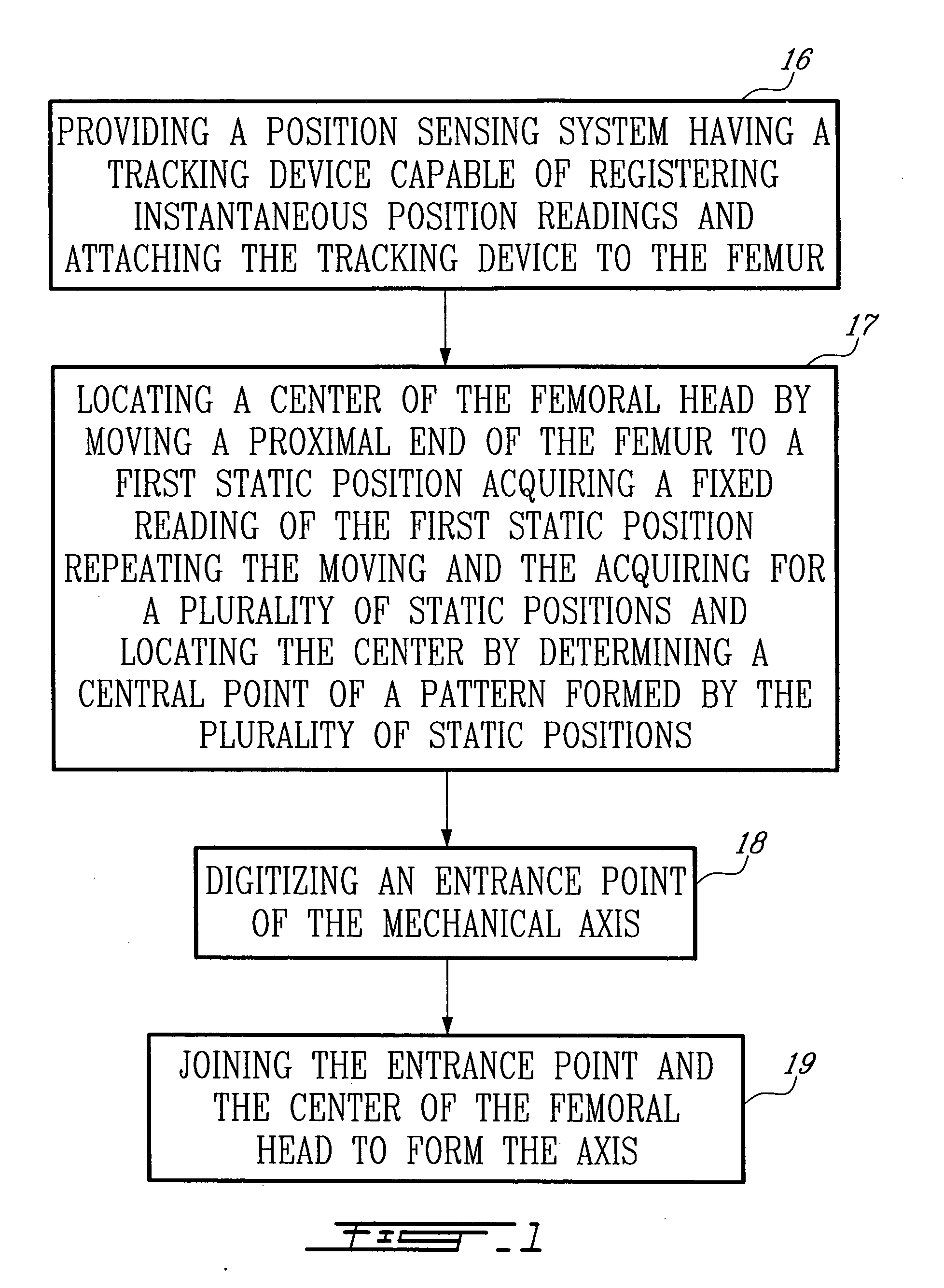
[0018]FIG. 1 is a flowchart describing the steps used to determine the mechanical axis of the femur bone during surgery. The first step is to provide a position sensing system having a tracking device capable of registering instantaneous position readings and attaching the tracking device to the femur 16. The next step is to locate the center of the femoral head 17. This point will be used in calculating the mechanical axis. To locate the center of the femoral he...


PUM


Abstract

There is described a method for determining a mechanical axis of a femur using a computer aided surgery system having an output device for displaying said mechanical axis, the method comprising: providing a position sensing system having a tracking device capable of registering instantaneous position readings and attaching the tracking device to the femur; locating a center of a femoral head of the femur by moving a proximal end of the femur to a first static position, acquiring a fixed reading of the first static position, repeating the moving and the acquiring for a plurality of static positions; and locating the centre by determining a central point of a pattern formed by the plurality of static positions; digitizing an entrance point of the mechanical axis at a substantially central position of the proximal end of the femur; and joining a line between the entrance point and the center of rotation to form the mechanical axis.

Description

FIELD OF THE INVENTION [0001] The invention relates to the field of computer-assisted surgery. More specifically, it relates to determining the mechanical axis of a femur and the center of a femoral head of femur during computer assisted surgery. BACKGROUND OF THE INVENTION [0002] While Computer-Tomographic(CT)-based Computer Assisted Surgery (CAS) systems are widely known in the art, CT-less CAS systems are slowly emerging as the technology of choice for North America and Europe. It is desirable to cut down the pre-operative time a surgeon must spend to prepare a surgery. It is also desirable to provide applications that can use other media than CT-scans, when these are not available. The CT-less system reduces pre-operative time and instrument calibration time, especially in simple surgeries, and in the case of more complex surgeries, the CT-less system can be combined with CT-based applications. [0003] A CT-less intra-operative bone reconstruction system advantageously provides a...

Claims


Application Information

Patent Timeline
IPC IPC(8): A61B5/103A61B17/15A61B19/00A61F2/46
CPCA61B5/103A61B5/1127A61B5/4504A61B17/154A61B19/52A61B19/5244A61F2/4657A61B2019/505A61B2019/5255A61B2019/5268A61B2019/5272A61F2/46A61B19/56A61B90/36A61B2034/2055A61B2034/2068A61B2034/2072A61B34/20A61B34/25A61B2034/105
Inventor RICHARD, ALAINJANSEN, HERBERT ANDREBROSSEAU, ERIC
Owner ORTHOSOFT ULC
Why Eureka
Try Eureka