Sterilized safety syringe

a safety syringe and sterilization technology, applied in the field of sterilization safety syringe, can solve the problem that the medical staff is sometimes inadvertently stung

Inactive Publication Date: 2005-01-20
YANG CHANG MING
View PDF3 Cites 78 Cited by
  • Summary
  • Abstract
  • Description
  • Claims
  • Application Information

AI Technical Summary

Benefits of technology

[0006] It is an object of the present invention to provide a sterilized safety syringe which can perfectly protect the medical personnel from being injured by the needle or infected by the residual body fluid in the syringe.

Problems solved by technology

Medicall staffs are sometime inadvertently stung by the needle he is handling or contaminated by the residual body fluid flowing out from the syringe that might become a cause of infection to the medical personnel.

Method used


Image

  • Sterilized safety syringe
  • Sterilized safety syringe
  • Sterilized safety syringe

Examples


Embodiment Construction

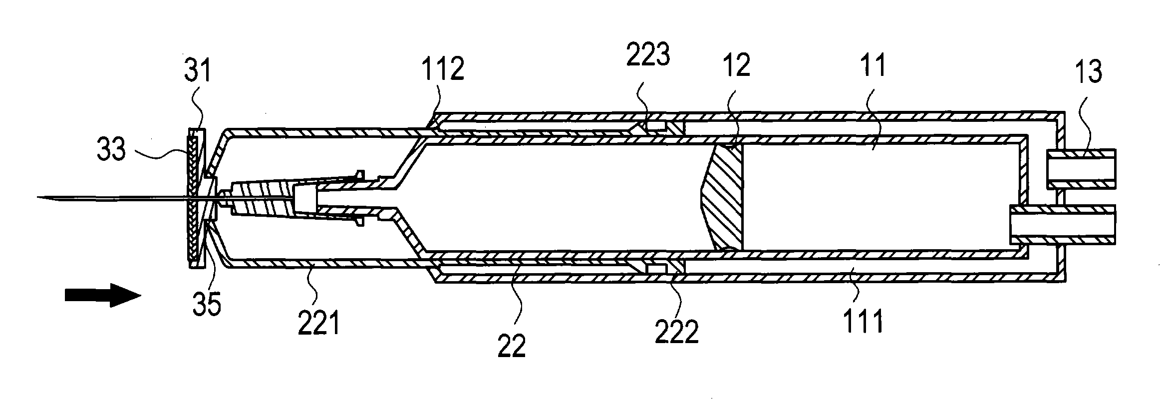
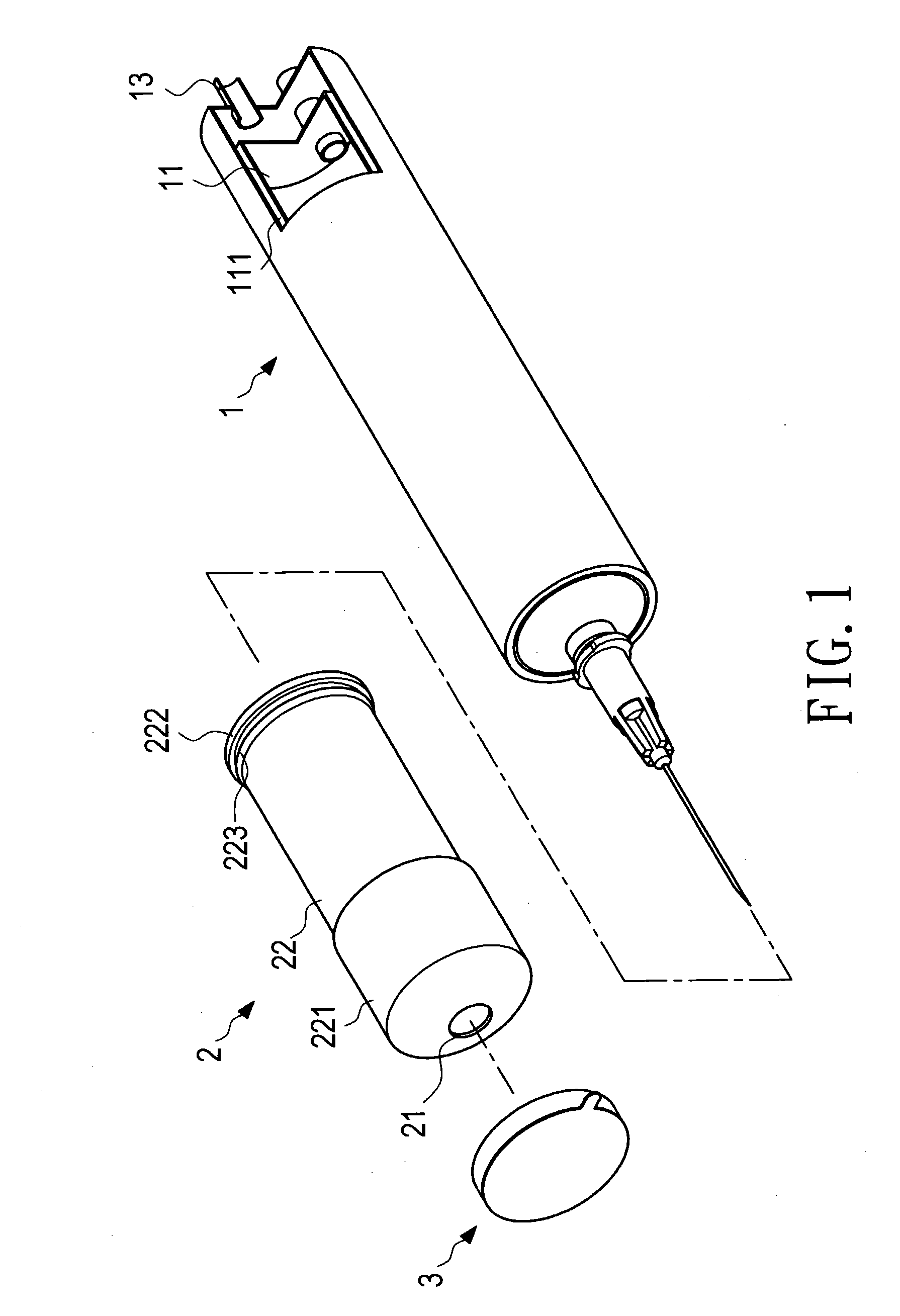
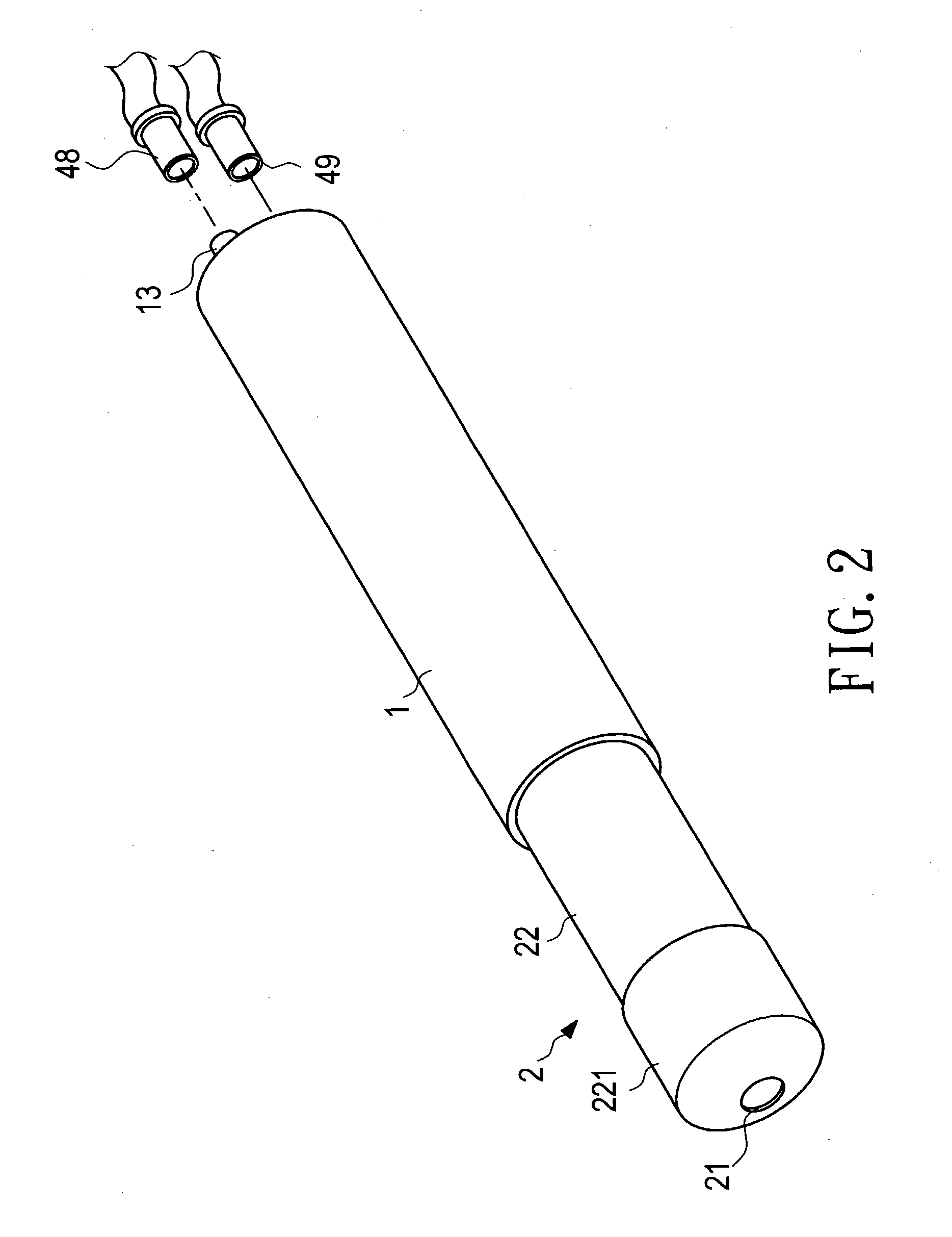
[0058] Referring to FIGS. 1, 2, 3, 4, 5, and 9, in the first embodiment, the sterilized safety syringe of the present invention essentially comprises a syringe tube 1, protective cover 2, a sterilizer 3, and an air compressor 4.

[0059] The syringe tube 1 contains a cavity 11 with a guide slot 111 formed between the outer surface and the inner wall of the syringe tube 1. The guide slot 111 passes through the front wall surface of the syringe tube 1, and has a Protrusion 112 at its front end. A plunger 12 is provided in the cavity 11 and is closely in contact with the inner wall surface of the cavity 11. The rear end of the syringe tube 1 is in a sealed state where its cavity 11 and the guide slot 111 are communicated with a plurality of air conducting pipes 13 of said air compressor via an air conducting pipe 13;

[0060] The protective cover 2 has a drilled hole 21 at its front end and is provided with more than one sliding plate 22 at its rear end thereof. Each of the sliding plates ...


PUM


Abstract

A sterilized safety syringe comprises a syringe tube, a protective cover, a sterilizer, and an air compressor. The protective cover is slid into a guide slot of the syringe tube with several sliding plates whose rear ends are closely in contact with the wall of the guide slot with their annular flanges. The syringe tube are equipped with several air conducting pipes which are connected with corresponding air feeding pipes of the air compressor. A plug is formed at the rear end of the sterilizer to be plugged into a drilled hole formed on the protective cover. Due to existence of perfectly effective sterilizer, the medical staffs never have to worry about infectant contamination brought about from inadvertent contact with the patient body fluid.

Description

BACKGROUND OF THE INVENTION [0001] 1. Field of the Invention [0002] The present invention relates to a sterilized safety syringe, and more particularly, to a sterilized safety syringe which can perfectly protect the medical staff from being injured and contaminated by the injection needle inadvertently when performing injection. [0003] 2. Description of the Prior Art [0004] A conventional medical syringe for injecting the drug solution into, or drawing the body fluid such as blood from the patient body is essentially composed of a syringe and an injection needle connected at its front end, and a tubular piston rod with a plunger telescopically slid in the syringe so as to infuse the drug solution into the patient body during its downward compression stroke, or draw the body fluid such as blood from the patient body into the syringe during its upward suction stroke. Before beginning the operation, a rubber band is used to bind around the portion immediately above the spot where the n...

Claims


Application Information

Patent Timeline
Patent Type & Authority Applications(United States)
IPC IPC(8): A61B5/15A61M5/00A61M5/20A61M5/31A61M5/315A61M5/32
CPCA61B5/1438A61M5/001A61M5/2053A61M5/31511A61M5/3243A61M2005/206A61M5/3272A61M2005/311A61M2005/3247A61M2205/50A61M5/326A61B5/15003A61B5/150229A61B5/150236A61B5/150244A61B5/150351A61B5/150389A61B5/150503A61B5/150656A61B5/150694A61B5/150717A61B5/150916A61B5/154
Inventor YANG, CHANG-MING
Owner YANG CHANG MING
Why Eureka
Try Eureka