Fuel tank installation

Active Publication Date: 2005-01-27
BAYERISCHE MOTOREN WERKE AG
View PDF1 Cites 11 Cited by
  • Summary
  • Abstract
  • Description
  • Claims
  • Application Information

AI Technical Summary

Benefits of technology

[0008] In this way, the operating vent lines can be blocked upon insertion of a refueling nozzle into the filler neck of a tank. The sensor signal may also be processed in a processor so as to provide for a delayed blocking of the vent line.
[0009] In a particular embodimen

Problems solved by technology

The vent line may be blocked still within the fuel tank, wherein the additional line connections needed for the blocking means would

Method used


Image

  • Fuel tank installation
  • Fuel tank installation

Examples


Embodiment Construction

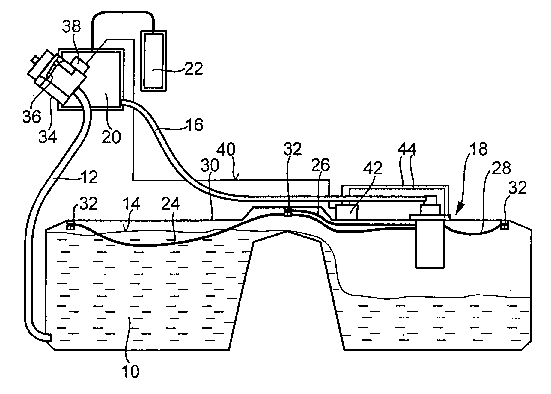
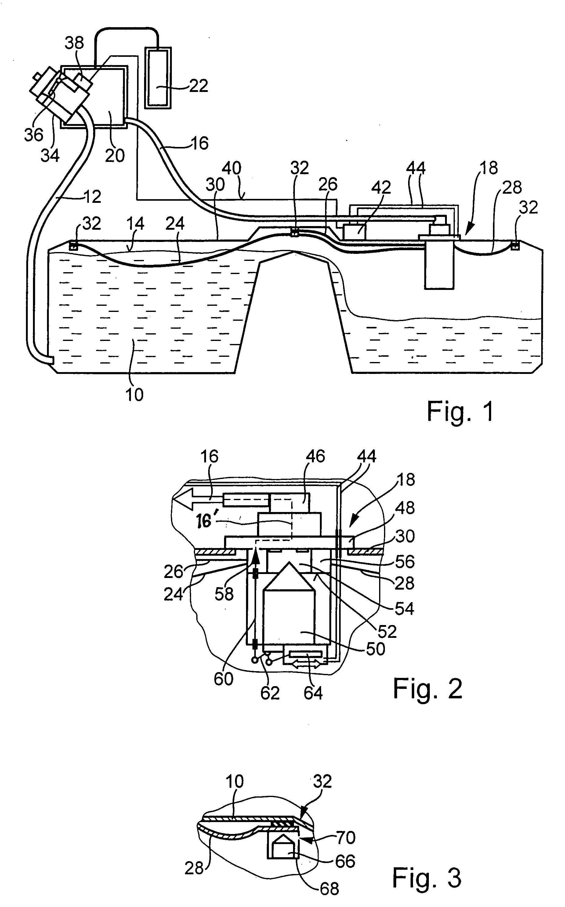
[0022]FIG. 1 shows schematically a fuel tank installation including a fuel tank 10 with a filler neck 12, which is connected to the fuel tank 10 below the maximum fill level 14 of the tank. In order to be able to vent the fuel tank 10 during refueling, a fill vent line 16 is provided, which is in communication, by way of a float valve 18, with the interior of the fuel tank 10 and also with an expansion container 20 and an activated carbon filter 22. When the fuel level in the fuel tank 10 reaches the maximum fill level 14, a float in the float valve 18 blocks communication between the fill vent line 16 and the interior of the fuel tank 10 so that it cannot be further filled. The fuel tank 10 is in the form of a so-called saddle tank and is shown in FIG. 1 to be three quarters full. As shown in FIG. 1, the left part of the saddle tank is filled to the maximum fill level 14. However, the float valve 18 which is arranged in the right part of the tank will terminate the refueling proces...


PUM

PropertyMeasurementUnit
Volumeaaaaaaaaaa
Areaaaaaaaaaaa

Abstract

In a fuel tank installation including a fuel tank with an expansion volume, a filler neck connected to the fuel tank for refueling, a fill vent line for venting the fuel tank during refueling and an operating vent line for venting the expansion volume of the tank, electrically operable valve means for blocking the operating vent line are arranged in a penetration area of the fuel tank where the operating vent line extends through the fuel tank.

Description

BACKGROUND OF THE INVENTION [0001] The invention relates to a fuel tank installation, particularly for a motor vehicle, comprising a fuel tank with a filler neck extending to the fuel tank, a fill vent line for venting the fuel tank during the filling procedure, an operating vent line for venting an expansion volume in the fuel tank above a maximum fill level and means for blocking the operating vent line particularly during the filling procedure. [0002] DE 34 42 149 A1 discloses a fuel tank installation wherein a fuel tank is provided with a filler neck connected to the fuel tank below the highest fill level of the fuel in the tank and with a fill vent line and several operating vent lines. The operating vent lines extend to a valve arranged in the area of the filler neck. Upon inserting a refueling nozzle into the filler neck, the valve is operated and closes the operating vent lines. In this way, the maximum fuel level in the fuel tank is determined solely by the location of the ...

Claims


Application Information

Patent Timeline
IPC IPC(8): B60K15/035F02M37/00
CPCB60K15/03504B60K15/03519B60K2015/03118F02M37/0094B60K2015/03533B60K2015/03571B60K2015/03576B60K2015/03509
Inventor ASCHOFF, WOLFGANGKRAUS, JURGENLIEBHART, WOLFGANG
Owner BAYERISCHE MOTOREN WERKE AG
Why Eureka
Try Eureka