Starting assembly for a carburetor
a carburetor and starting assembly technology, applied in the field of carburetors, can solve the problems of increasing engine rpm, unstable idle operation, and difficult engine start, and achieve the effects of facilitating cold start of the engine, increasing fuel flow, and increasing air flow
- Summary
- Abstract
- Description
- Claims
- Application Information
AI Technical Summary
Benefits of technology
Problems solved by technology
Method used
Image
Examples
second embodiment
[0078] Second Embodiment
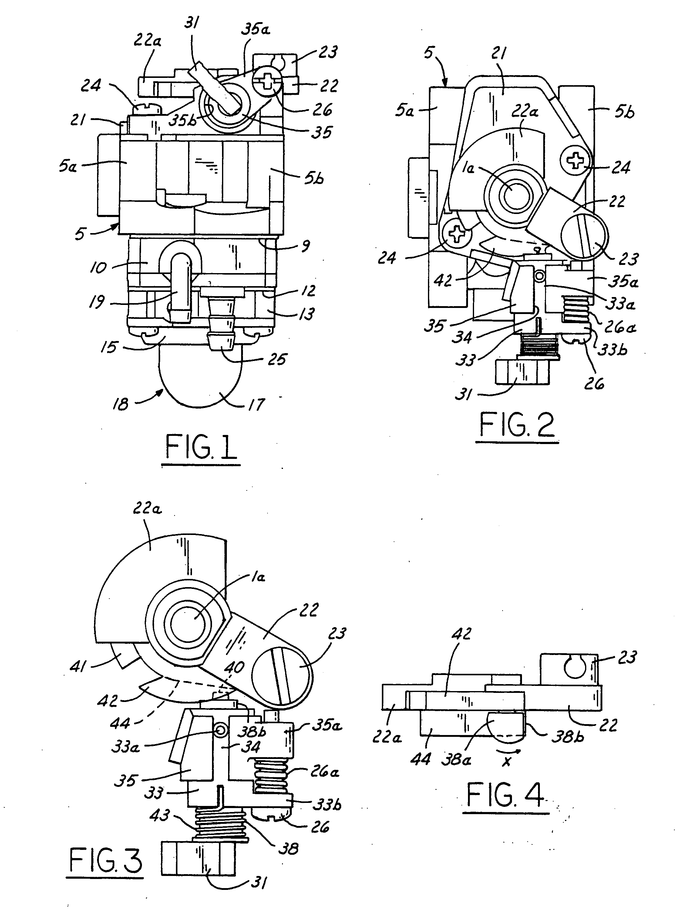
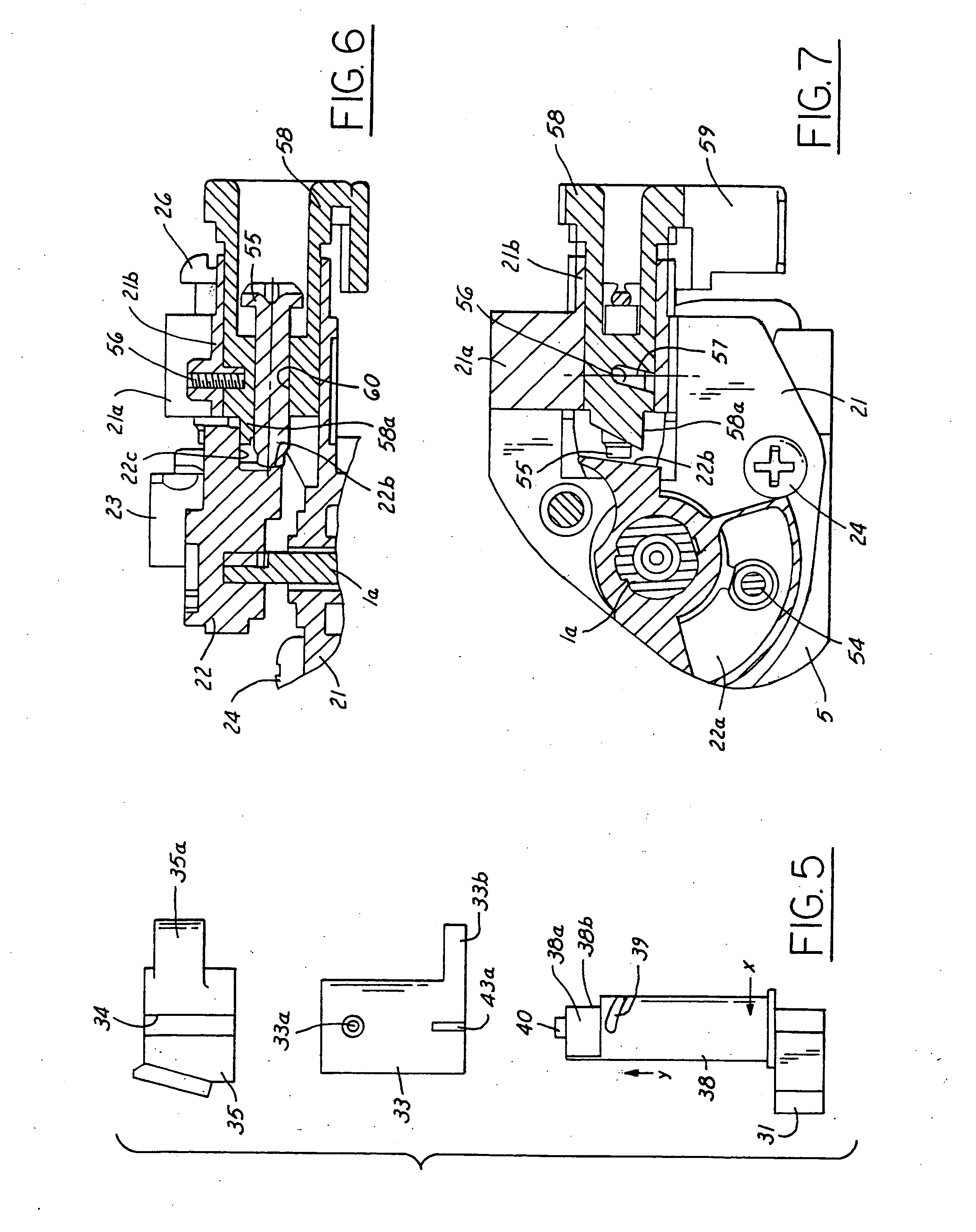
[0079] In the embodiment shown in FIGS. 6 to 8, the lid plate 21 for closing the valve chamber is fixed on the carburetor body 5 by a plurality of bolts 24, and the throttle valve lever 22 is connected to the upper end of the valve shaft 1a extending through the lid plate 21. As shown in FIG. 8, the valve shaft 1a is covered with a dust-proof boot 1b. The swivel 23 is supported on the end of the throttle valve lever 22, a cam portion 22a is formed integral with the other end thereof. A cam groove in engagement with a follower 54 projecting from the lid plate 21 is provided in the cam portion 22a, as shown in FIGS. 6 and 7. A projecting wall 22b is projected downward from the lower surface 22c of the throttle valve lever 22. The idling adjusting bolt 26 is threadedly fitted in a projecting wall 21a which is projected upward from a side edge of the lid plate 21. A boss portion or a guide tube 21b is formed integral with the lid plate 21, especially adjacent to ...
third embodiment
[0082] Third Embodiment
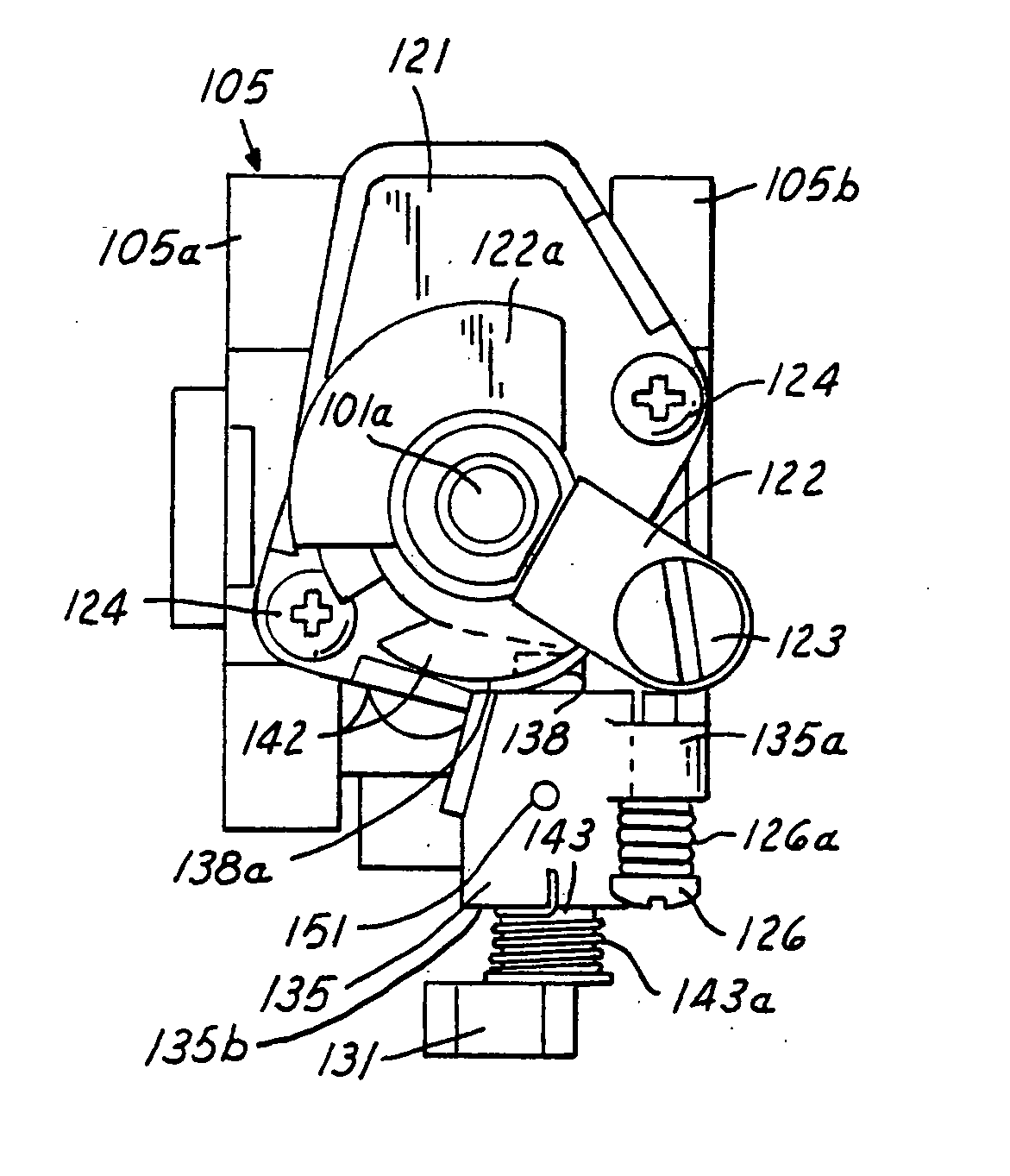
[0083] In the embodiment shown in FIGS. 9 and 10, a lid plate 121 is put on the upper surface of the carburetor body 105 and secured thereto by means of bolts 124. A throttle valve lever 122 having a quadrant-shaped cam 122a is connected to the upper end of a valve shaft 101a of a throttle valve, the valve shaft 101a extending upwardly through the lid plate 121. The throttle valve lever 122 is normally placed in contact with an idling adjusting bolt 126 by the force of a return spring, not shown. The throttle valve lever 122 is provided with a cam plate 142 and an outwardly extending projection 142a is formed on the outer edge of the cam plate 142.
[0084] A start shaft 143 is fitted into an axial hole 135b of a guide tube 135 which is connected to the lid plate 121 or formed integral with the lid plate 121. A pin 151 mounted on the guide tube 135 is engaged with an annular groove formed on the start shaft 143. An idling adjusting bolt 126 having a locking spri...
fourth embodiment
[0090] Fourth Embodiment
[0091] Another embodiment carburetor is shown in FIGS. 11 to 19. As shown in FIGS. 11 and 12, the rotary throttle valve-type carburetor provided with a starting device has a carburetor body 220 made of aluminum and provided with an air intake passage 218 extending therethrough and a pair of left and right through-holes 212 provided on front and rear end flanges of the carburetor body 220, respectively. An air cleaner is connected on the front end flange in FIG. 11, and the rear end flange is connected through a heat insulating pipe to the wall surrounding an intake port of the engine by a pair of bolts extending through the through-holes 212. A throttle valve 219 having a throttle hole is rotatably and vertically movably fitted into a cylindrical valve chamber perpendicular to the air intake passage 218. A valve shaft 206 extends from the upper end of the throttle valve 219, through a lid plate 202 that is preferably formed of synthetic resin, for closing the...
PUM
| Property | Measurement | Unit |
|---|---|---|
| flow area | aaaaa | aaaaa |
| distance | aaaaa | aaaaa |
| area | aaaaa | aaaaa |
Abstract
Description
Claims
Application Information
 - R&D
- Intellectual Property
- Life Sciences
- Materials
- Tech Scout
- Unparalleled Data Quality
- Higher Quality Content
- 60% Fewer Hallucinations
Browse by: Latest US Patents, China's latest patents, Technical Efficacy Thesaurus, Application Domain, Technology Topic, Popular Technical Reports.
© 2025 PatSnap. All rights reserved.Legal|Privacy policy|Modern Slavery Act Transparency Statement|Sitemap|About US| Contact US: help@patsnap.com


