Ophthalmic photographic apparatus

a technology of ophthalmic photography and ophthalmic lens, which is applied in the field of ophthalmic photographic equipment, can solve the problems of increasing the length of the optical system, difficult to arrange the photographic mask at the imaging plane, and high cost of camera hardwar

Inactive Publication Date: 2005-01-27
KOWA CO LTD +1
View PDF2 Cites 34 Cited by
  • Summary
  • Abstract
  • Description
  • Claims
  • Application Information

AI Technical Summary

Benefits of technology

[0011] To attain the above object, the invention provides an ophthalmic photographic apparatus that uses electronic imaging means to photograph an image of a fundus of an eye to be examined, wherein interlocking means are provided to move an photographic mask for defining a fundus photography range and / or a photographic stop for eliminating light reflected from an anterior portion of the eye in an interlocked manner relative to the movement of the focusing lens in such a way that with respect to a photographic optical system the photographic mask may be kept at a position substantially conjugate with an imaging plane of the electronic imaging means and / or the photographic stop may be kept at a position substantially conjugate with an anterior portion of the eye.

Problems solved by technology

This has made it unnecessary to separately provide a fundus-conjugate position that is on the image side of the focusing lens.
However, because the imaging (image-formation) plane is not on the surface of the imaging device in the case of an electronic camera, it is very difficult to arrange the photographic mask at its imaging plane.
If there was a desire to employ an imaging device that included a photographic mask on its imaging plane, it would be necessary to manufacture the imaging device incorporating the required mask that met the requisite size and other criteria beforehand, which would make the camera hardware very costly.
If, however, the mask is provided on a fundus-conjugate position somewhere else between the focusing lens and the imaging plane, it would increase the length of the optical system, which, together with the need for a relay lens, makes it more difficult to achieve the light weight and small size that are the desirable attributes for a portable fundus camera.

Method used


Image

  • Ophthalmic photographic apparatus
  • Ophthalmic photographic apparatus

Examples


Embodiment Construction

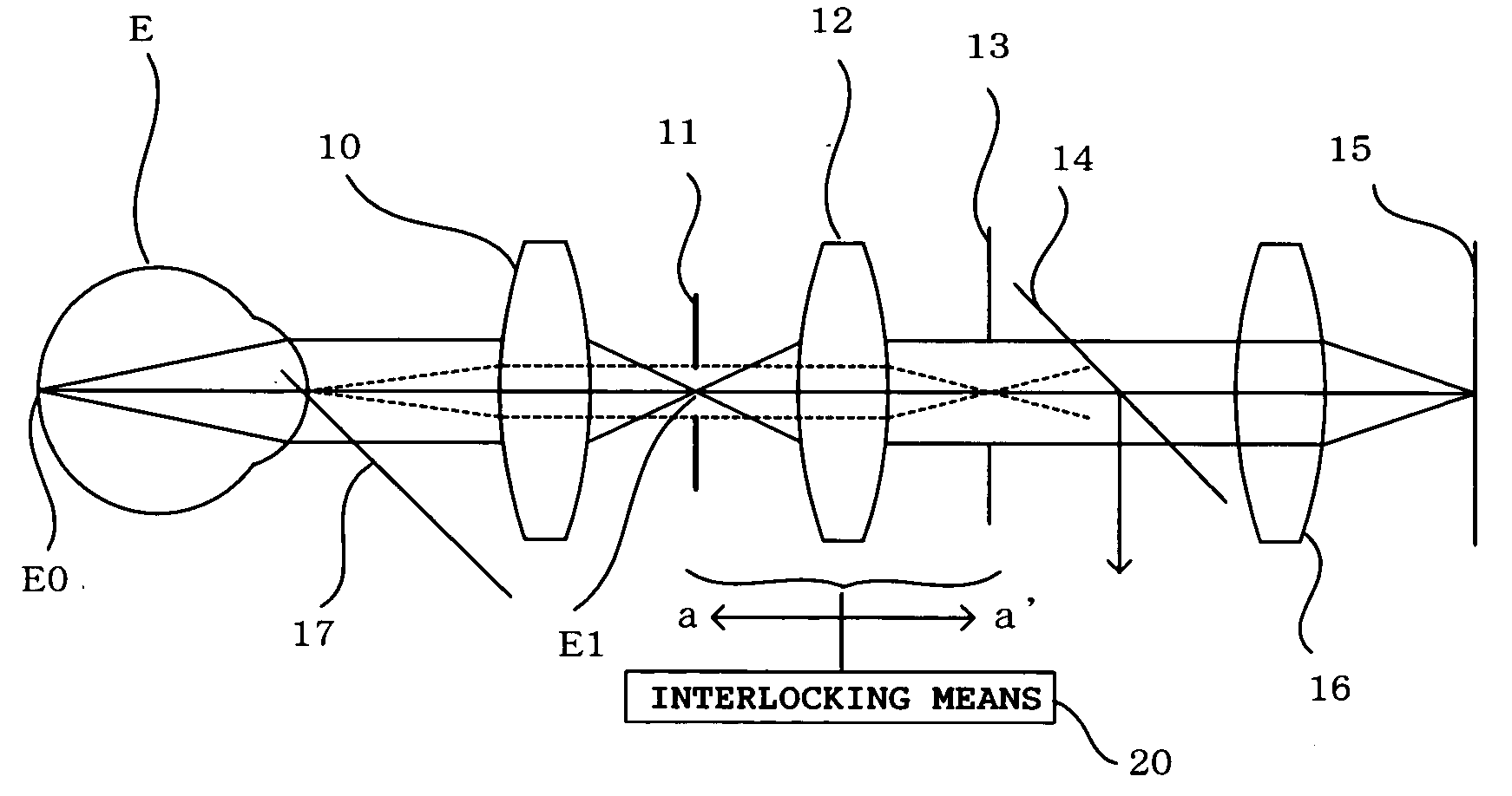
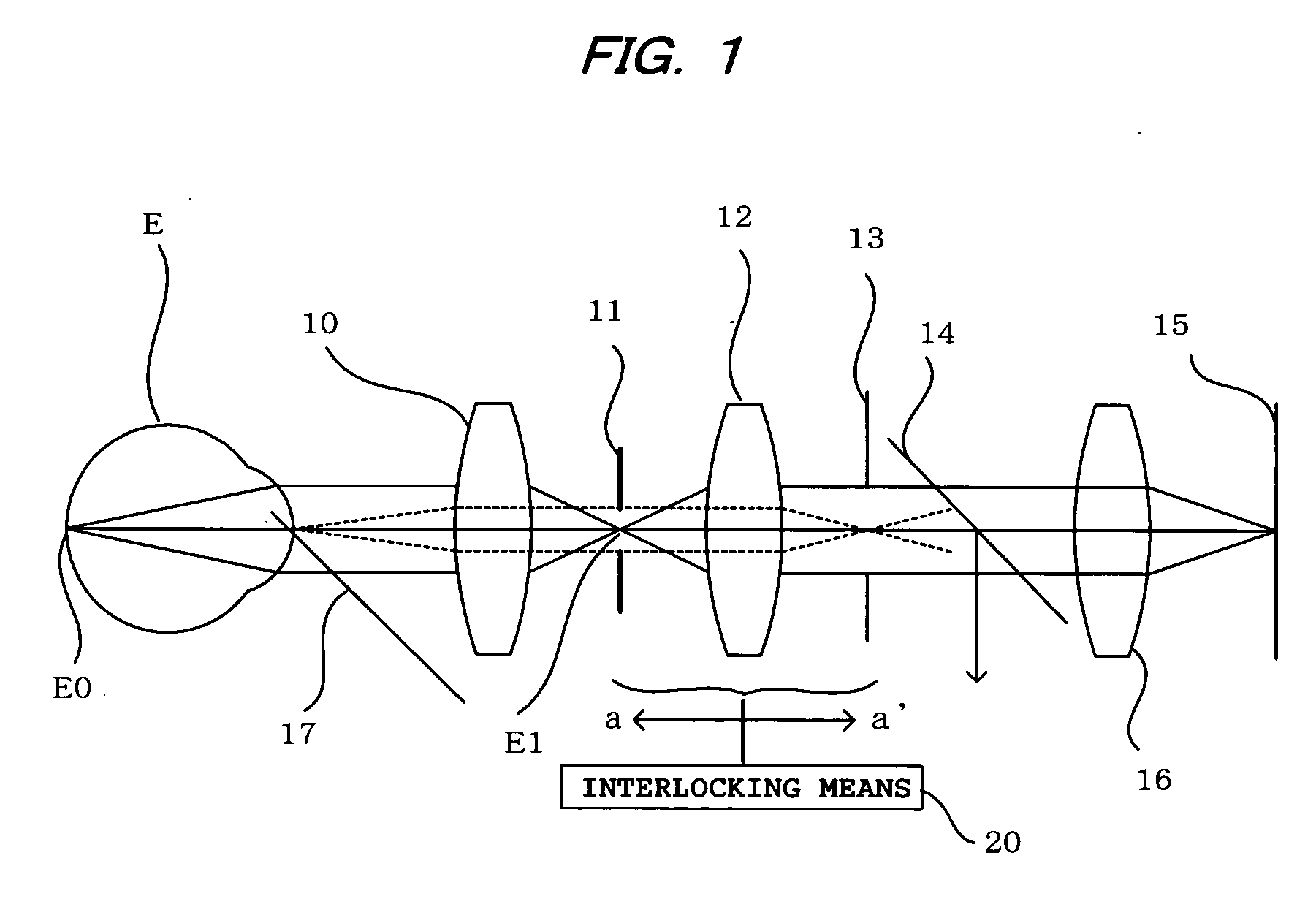
[0014] The embodiment of the present invention will now be described with reference to FIG. 1, which shows the optical system of an eye fundus camera. The fundus camera shown in FIG. 1 is a portable type that uses a CCD imaging device. However, it is to be understood that the invention is not limited to a CCD imaging device, but can use an imaging system based on other imaging devices such as a CMOS sensor or the like.

[0015] In FIG. 1, symbol E denotes the subject eye to be examined, and reference numerals 10 to 16 denote the parts that make up the optical system of the fundus camera. In the drawing, the optical system axis is coincident with the optical axis of the eye.

[0016] The illumination optical system axis 17 is shown to the front of an objective lens 10. The illumination optical system itself is not shown, but can be a conventional type used in existing portable fundus cameras in which optical means such as prisms are used to illuminate the anterior portion of the eye E wi...


PUM


Abstract

An ophthalmic photographic apparatus comprises a photographic mask for defining a fundus photography range, a photographic stop for eliminating light reflected from an anterior portion of the eye, and a focusing lens for bringing the fundus into focus. Interlocking means are provided to move the photographic mask and the photographic stop in an interlocked manner relative to the movement of the focusing lens in such a way that with respect to a photographic optical system the photographic mask may be kept at a position substantially conjugate with an imaging plane of a CCD and the photographic stop may be kept at a position substantially conjugate with an anterior portion of the eye. The CCD is located at the image-side focal plane of the image-formation lens, the mask is located on the object-side focal plane of the focusing lens, and the photographic stop is located on the image-side focal plane of the focusing lens. These three components are moved as one unit when the system is adjusted to focus on the fundus.

Description

BACKGROUND OF THE INVENTION [0001] 1. Field of the Invention [0002] The present invention relates to an ophthalmic photographic apparatus that uses electronic imaging means to photograph an image of a fundus of an eye to be examined. [0003] 2. Description of the Prior Art [0004] A portable fundus camera is well known, generally either having a construction in which a part required for photographic operation such as at least part of the optical system used for observation and photography is separate, allowing it to be carried by the examiner, or a construction in which, if possible, all the camera components are housed in a case that can be carried. Japanese Patent Laid-open Publication No. 256726 / 92 describes the former type of fundus camera. [0005] Because photographic images recorded by a fundus camera are used for making medical diagnoses, the images have to be reliable. For example, it is necessary to ensure that the images that are photographed do not include images of reflecte...

Claims


Application Information

Patent Timeline
Patent Type & Authority Applications(United States)
IPC IPC(8): A61B3/14A61B3/15
CPCA61B3/156A61B3/145
Inventor MAEDA, NAOKIMATSUMURA, KAZUNORITAKIMOTO, SHIGERU
Owner KOWA CO LTD
Why Eureka
Try Eureka