
Image-recording apparatus using spatial light-modulation device on which divided reset actuation is performed

a technology of spatial light and actuation device, which is applied in the direction of visual presentation using printers, instruments, optical elements, etc., can solve the problems of difficult to increase scanning speed, difficult to increase scanning resolution in the scanning direction, and take a long time to complete resetting operations, so as to reduce the time necessary to update the spatial light-modulation device can be further reduced. , the effect of reducing the time necessary to upda

Inactive Publication Date: 2005-01-27
FUJIFILM HLDG CORP +1
View PDF4 Cites 25 Cited by
  • Summary
  • Abstract
  • Description
  • Claims
  • Application Information

AI Technical Summary

Benefits of technology

A first object of the present invention is to provide an image-recording method which can reduce the time necessary to update a spatial light-modulation device.
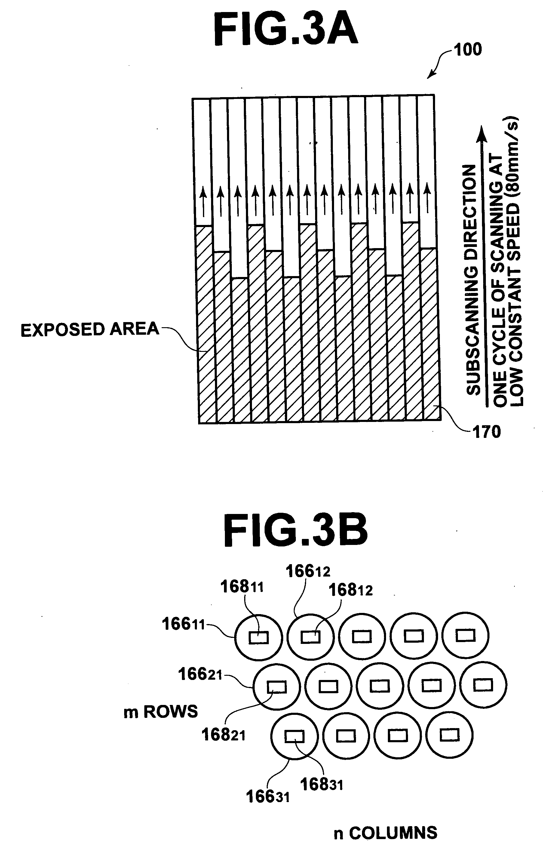
Moreover, when the spatial light-modulation device is arranged in the image-recording head in such a manner that the lines of image-recording elements in the spatial light-modulation device form with the scanning direction of the image-recording head a predetermined angle greater than zero, and the image is recorded with the image-recording head on the image-recording plane by performing multiple recording operations with a multiplicity of N (which is a natural number greater than one), and image-recording points recorded by using the spatial light-modulation device are shifted in the scanning direction by an amount which is predetermined for each of the plurality of regions, it is possible to increase the resolution in the scanning direction without decreasing the scanning speed, as explained later in detail.

Problems solved by technology

Therefore, sometimes it takes a long time until the resetting operations are completed.
However, since the times necessary to update micromirrors cause a bottleneck, it is difficult to increase the scanning speed.
In addition, it is also difficult to increase the resolution in the scanning direction while maintaining the scanning speed.

Method used


Image

  • Image-recording apparatus using spatial light-modulation device on which divided reset actuation is performed
  • Image-recording apparatus using spatial light-modulation device on which divided reset actuation is performed
  • Image-recording apparatus using spatial light-modulation device on which divided reset actuation is performed

Examples


Embodiment Construction

An embodiment of the present invention will be described in detail below with reference to the attached drawings. Although numerical values are indicated in the following descriptions, the present invention is not limited to such numerical values.

Construction of Exposure System

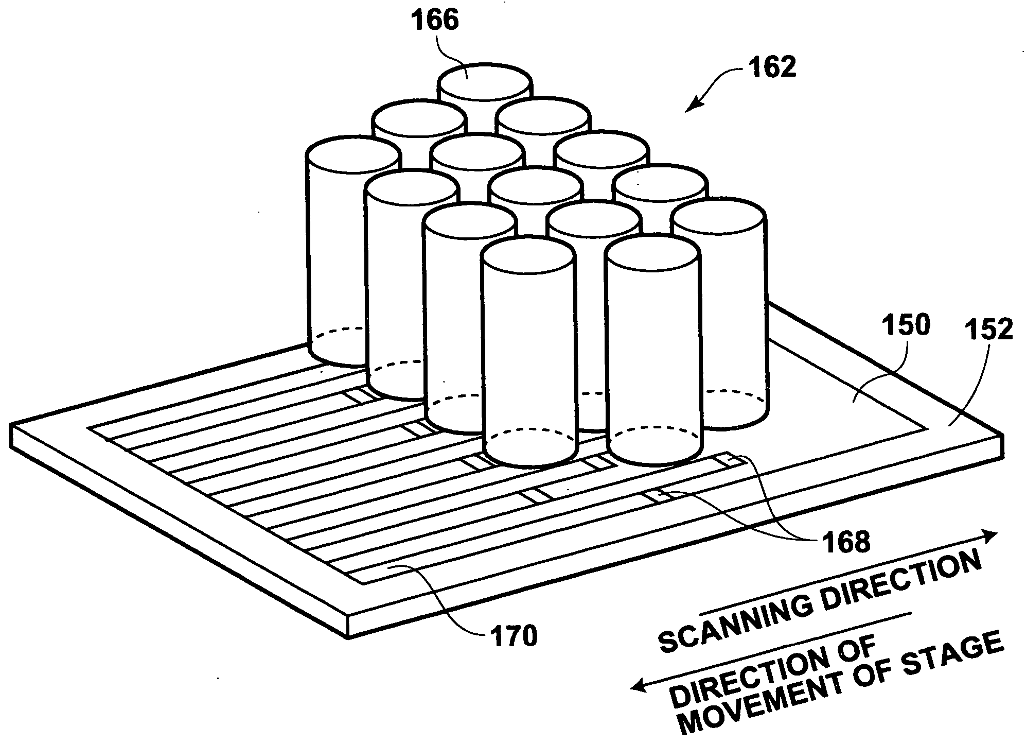
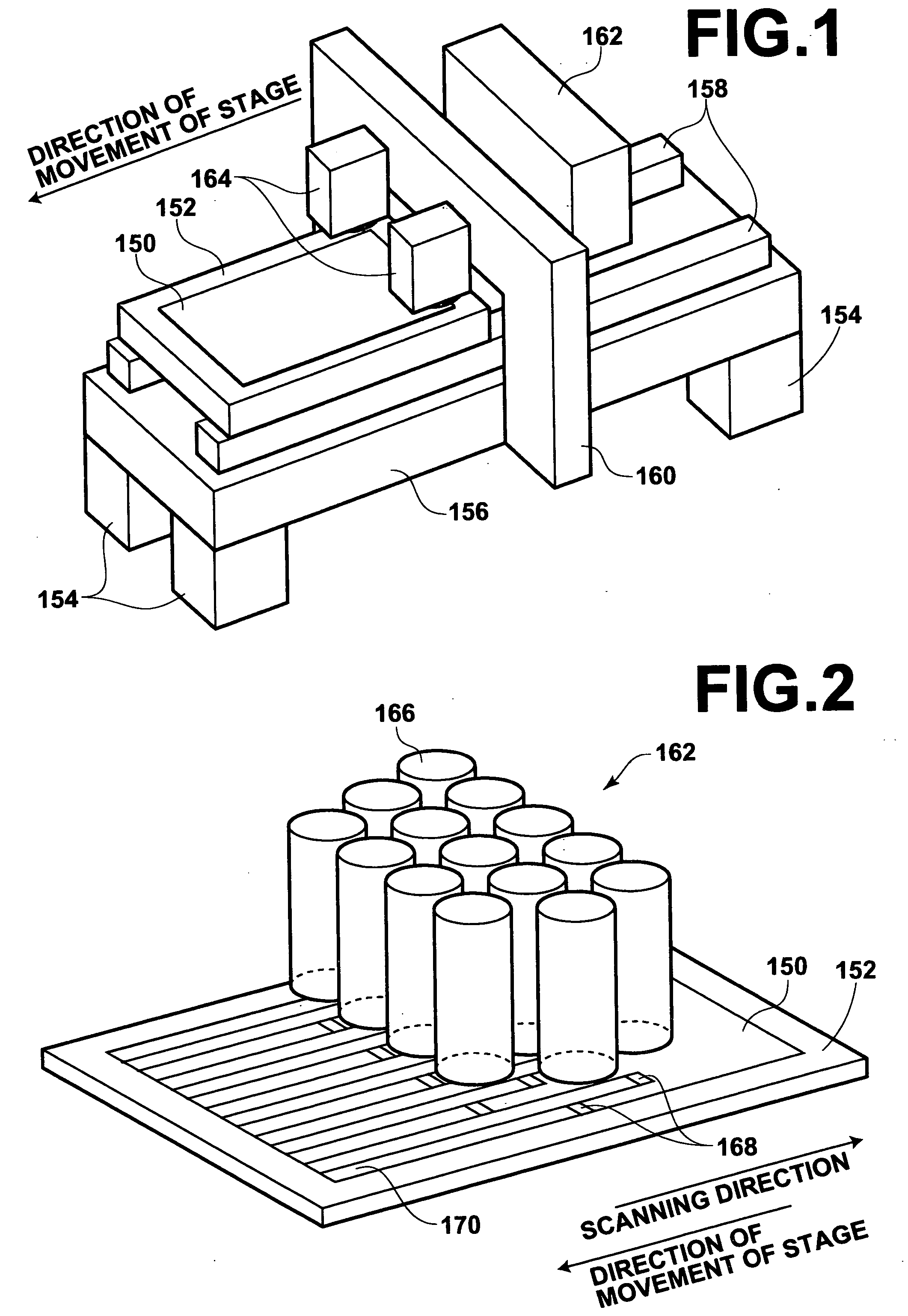
The image-recording apparatus according to an embodiment of the present invention is an exposure system of a so-called flat-head type. As illustrated in FIG. 1, the image-recording apparatus comprises a stage 152, which holds a photosensitive sheet 150 on its surface by suction. Two guides 158 extending in a direction along which the stage moves are arranged on an upper surface of a mount table 156, which is formed of a thick plate supported by four legs 154. The stage 152 is placed on and supported by the guides 158 so that the length direction of the stage 152 corresponds to the direction along which the stage 152 moves, and the stage 152 can move in either direction. In addition, the exposure system of...


PUM


Abstract

In an image-recording apparatus: an image-recording head relatively moves with respect to an image-recording plane in a predetermined direction, and modulates incident light with a spatial light-modulation device containing a plurality of rows of image-recording elements, and each of the image-recording elements modulates the incident light according to one of control signals; and a control unit outputs ones of the control signals to each of a plurality of regions of the spatial light-modulation device each containing at least one of the plurality of rows of image-recording elements, on a region-by-region basis in succession, and controls image-recording elements in each of the plurality of regions on a region-by-region basis so that the image-recording elements in each of the plurality of regions start modulation of the incident light when an operation of inputting the ones of the control signals into the region is completed.

Description

BACKGROUND OF THE INVENTION 1. Field of the Invention The present invention relates to an image-recording apparatus in which an image-recording head having a spatial light-modulation device is relatively moved with respect to an image-recording plane in a predetermined direction along the image-recording plane, where a great number of rows of image-recording elements are arranged in the spatial light-modulation device, a great number of image-recording elements are arranged along a line in each row of image-recording elements, and each image-recording element modulates incident light according to an inputted control signal. The present invention also relates to an image-recording method using the above image-recording apparatus. 2. Description of the Related Art The following documents (1) and (2) disclose information related to the present invention. (1) U.S. Pat. No. 6,201,521 (2) U.S. Patent Laid-Open No. 20020092993 Conventionally, various exposure systems in which images ...

Claims


Application Information

Patent Timeline
IPC IPC(8): B41J2/44B41J2/01B41J2/45B41J2/455B41J2/465G02B26/08G03F7/20G06K15/12H01L21/027H05K3/00
CPCG06K15/1252B41J2/465G03F7/20
Inventor NAKAYA, DAISUKEFUJII, TAKESHISHIMOYAMA, YUJI
Owner FUJIFILM HLDG CORP
Learn More