Acoustic-propagation-time measuring apparatus

a technology measuring apparatus, which is applied in the direction of specific gravity measurement, using reradiation, instruments, etc., can solve the problems of high accuracy of acoustic propagation time analytic measurement, distance, distance difference (gap), and the inability to accurately inspect the target object b>1/b> with a known sonar device, etc., to achieve the effect of correcting the high-accuracy analytic measurement o

Active Publication Date: 2005-01-27
KK TOSHIBA
View PDF10 Cites 24 Cited by
  • Summary
  • Abstract
  • Description
  • Claims
  • Application Information

AI Technical Summary

Benefits of technology

In view of the circumstances encountered in the prior art mentioned above, an object of the present invention is to provide an acoustic-propagation-time measuring a...

Problems solved by technology

Referring to FIG. 10, if a target object 1 to be measured has a bump or irregular (having protrusions and recesses) measuring surface thereon, is complicated in shape, or suffers from a complicated defect, the bump surface or shape cannot be measured correctly or the defect on the target object 1 cannot be accurately inspected with a known sonar device.
Referring to FIG. 11B, however, if the target object 1 to be mea...

Method used


Image

  • Acoustic-propagation-time measuring apparatus
  • Acoustic-propagation-time measuring apparatus
  • Acoustic-propagation-time measuring apparatus

Examples


second embodiment

FIG. 5 is an outline block diagram showing an acoustic-propagation-time measuring apparatus according to the present invention.

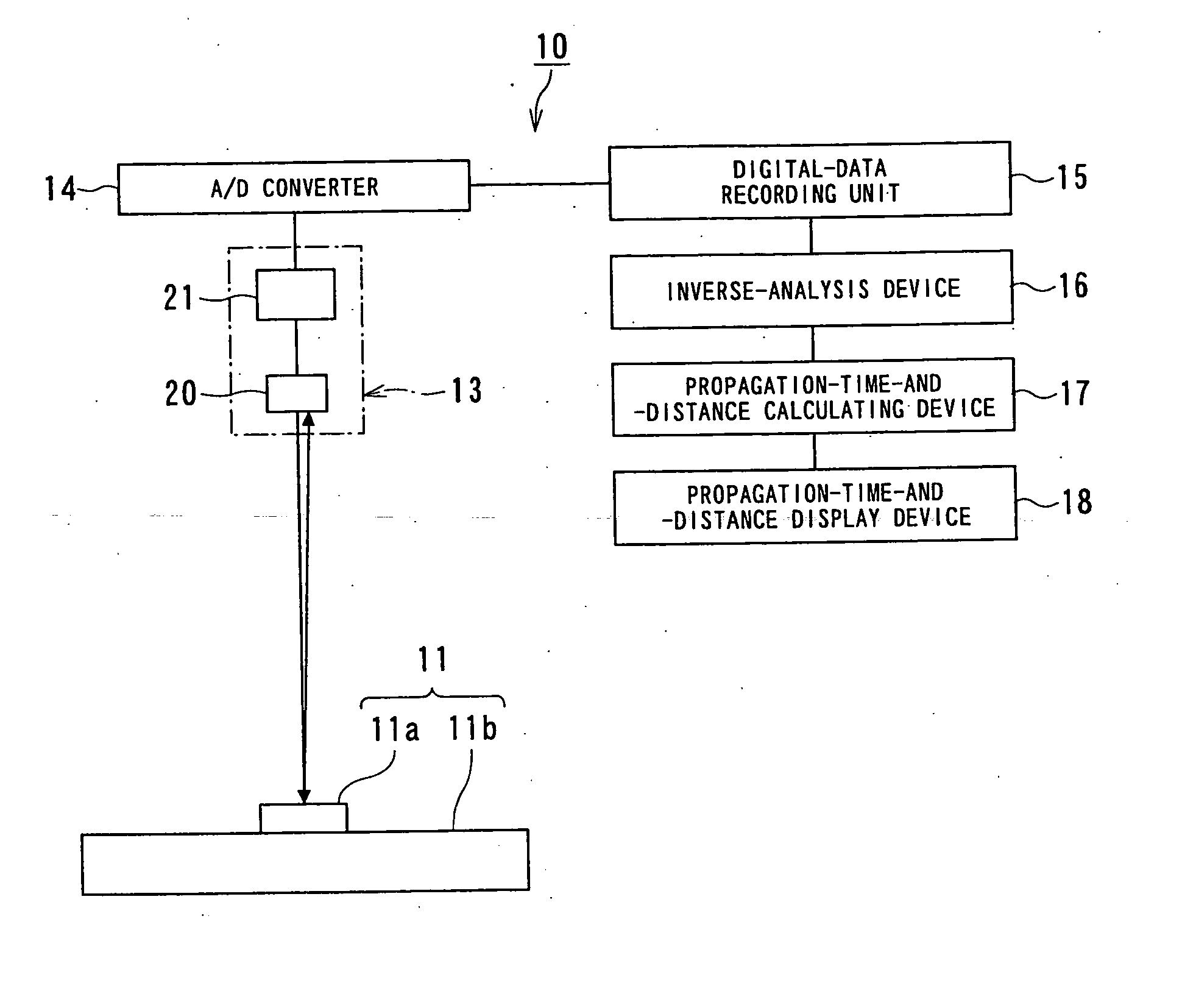
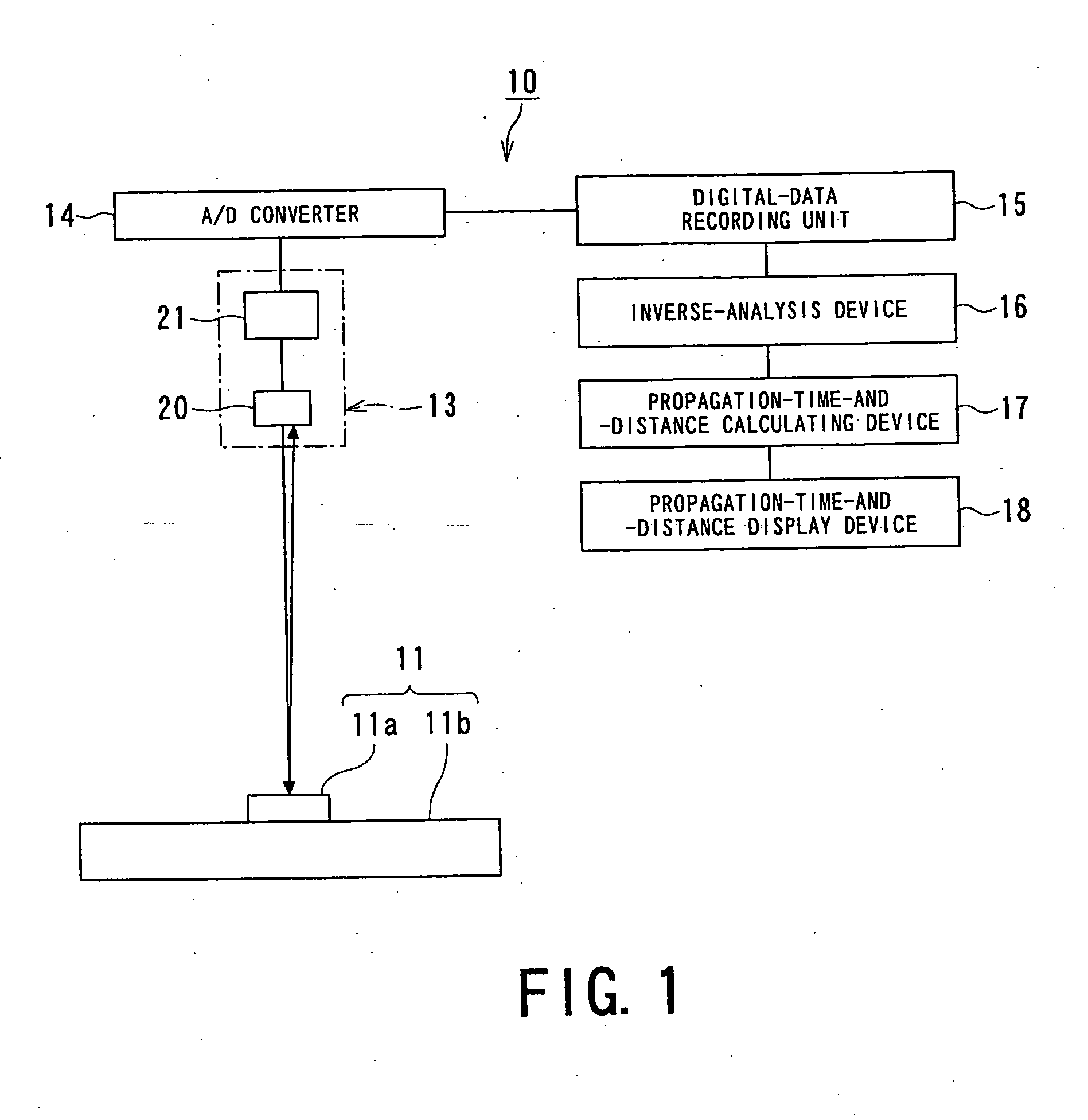
An acoustic-propagation-time measuring apparatus 10A of this second embodiment basically has the same structure as that of the acoustic-propagation-time measuring apparatus (distance-measuring apparatus) 10 of the first embodiment shown in FIG. 1, except that the acoustic-propagation-time measuring apparatus 10A is provided with a transmitting and receiving device 13A. The same components as those of the acoustic-propagation-time measuring apparatus 10 are denoted by the same reference numerals and will not be described here.

This acoustic-propagation-time measuring apparatus 10A is applied to a distance-measuring apparatus utilizing acoustic wave, and the transmitting and receiving device 13A includes a plurality pairs of the acoustic element 20 and the emitting and receiving unit 21. An impulse voltage may be applied to the plurality of acoustic elements...

third embodiment

FIG. 6 is an outline block diagram showing an acoustic-propagation-time measuring apparatus according to the present invention.

An acoustic-propagation-time measuring apparatus 10B according to this third embodiment has basically the same structure as that of the first embodiment shown in FIG. 1, except that the measuring apparatus 10B additionally includes a noise filter 25. The same components as those of the acoustic-propagation-time measuring apparatus 10 are denoted by the same reference numerals and will not be described.

The noise filter 25 is provided between the digital-data recording unit 15 and the inverse-analysis device 16. With this noise filter 25, noise is eliminated from the digital echo signal E, i.e., an acoustic receiving signal at the signal input end of the inverse-analysis device 16. After the acoustic-propagation-time measuring apparatus 10B is thus made resistive to noise, calculation errors during the inverse analysis can be reduced. Furthermore, with the ...

fourth embodiment

FIG. 7 shows an acoustic-propagation-time measuring apparatus according to the present invention.

An acoustic-propagation-time measuring apparatus 10C according to this fourth embodiment has basically the same structure as that of the third embodiment shown in FIG. 6, except that the measuring apparatus 10C additionally includes an inverse-analysis correcting device 27. The same components as those of the acoustic-propagation-time measuring apparatus 10B shown in FIG. 6 are denoted by the same reference numerals and will not be described.

The acoustic-propagation-time measuring apparatus 10C shown in FIG. 7 additionally includes the noise filter 25 and the inverse-analysis correcting device 27, compared with the acoustic-propagation-time measuring apparatus 10 of the first embodiment shown in FIG. 1. The noise filter 25 is provided between the digital-data recording unit 15 and the inverse-analysis device 16, and the inverse-analysis correcting device 27 is provided between the inv...


PUM


Abstract

An acoustic-propagation-time measuring apparatus includes an acoustic transmitting and receiving section having an acoustic element capable of transmitting and receiving acoustic waves, an A/D converter which converts an echo signal reflected from a target object to be measured into a digital signal, an inverse-analysis section that converts the digital echo signal into an impulse signal through inverse analysis where the digital echo signal is multiplied by an inverse matrix, a calculating section that measures an acoustic propagation time and a time difference based on the digital echo signal converted to the impulse signal, and a display section which displays the acoustic propagation time and time difference calculated by the calculating section.

Description

BACKGROUND OF THE INVENTION 1. Field of the Invention The present invention relates to acoustic-propagation-time measuring apparatuses capable of performing high-accuracy analytic measurement of an acoustic propagation time in a fluid or solid. In particular, the present invention relates to an acoustic-propagation-time measuring apparatus capable of measuring the distance to an object to be measured and the distance distribution by measuring an acoustic propagation time. 2. Related Art One conventional example of an acoustic-propagation-time measuring apparatus is a sonar device described in Japanese Patent Laid-open (KOKAI) Publication No. 2003-139855. The sonar device described in this reference includes transmitting and receiving means having a plurality of ultrasound transducers. The sonar device emits an ultrasound signal from this transmitting and receiving means to an object and receives a reflected wave with the ultrasound transducers, realized by a plurality of receiv...

Claims


Application Information

Patent Timeline
IPC IPC(8): G01N29/07G01H5/00G01N29/52G01S7/526G01S7/527G01S15/00G01S15/10G01S15/42
CPCG01N29/069G01N29/07G01N29/449G01S15/42G01N2291/02854G01N2291/101G01S7/527G01N29/52
Inventor KOMAI, MASAFUMINAGAI, SATOSHISUZUKI, TAKEHIKO
Owner KK TOSHIBA
Why Eureka
Try Eureka