
Ribbed module for wave energy dispersion

a technology of wave energy and ribbed modules, which is applied in the direction of piers, special-purpose vessels, groynes, etc., can solve the problems of reducing the wave energy, and reducing the effect of wave action on the shor

Inactive Publication Date: 2005-01-27
WAVE DISPERSION TECH
View PDF25 Cites 0 Cited by
  • Summary
  • Abstract
  • Description
  • Claims
  • Application Information

AI Technical Summary

Benefits of technology

[0014] It is an object of the present invention to provide a module constructed to dissipate energy from flowing water regardless of the amount of water or the size of any waves, such that erosion of a shoreline is substantially reduced if not eliminated.
[0043] The objects of the present invention are accomplished by providing a module constructed with a plurality of ribbed surfaces and channels arranged to fracture a wave impinging thereon and direct the wave into eddies and vortices which interfere with each other to substantially reduce the wave energy. Pairs of mating modules are joined together with a unique connection assembly. A plurality of such modules are connected to form breakwaters which reduce the effects of wave action on the shore.

Problems solved by technology

Traditional breakwaters, sea walls and jetties have failed to substantially curtail the destructive force of moving water primarily because of their construction, and tendencies to reflect or direct wave energy in destructive ways or concentrate the energy in local hot spots.
Erosion and the scouring effects of the misdirected energy lead to the loss of the beach and undermining of the structures which were meant to protect the shoreline.
In addition, other fixed structures such as groins lead to the loss of natural flows and downdrift beaches by interrupting the littoral flows and generally create a surplus condition on the updraft side and a starvation condition on the downdraft beaches.
Other erosion control systems which are positioned offshore do not provide the arrangement of surfaces which deflect and redirect breaking waves so that eddies and vortexes produced interfere with and cancel each other, as well as the oncoming portions of the next successive wave.
Many of these known devices and systems are rigidly mounted to the shore or shelf portion underneath the surf in a manner which severely restricts, if not eliminates, removal of the system to another location where the barriers are needed more urgently.
These same systems also usually require an extensive and expensive environmental impact study to justify use of the systems in marine environments which are essentially classified as “sensitive”.

Method used


Image

  • Ribbed module for wave energy dispersion
  • Ribbed module for wave energy dispersion
  • Ribbed module for wave energy dispersion

Examples


Embodiment Construction

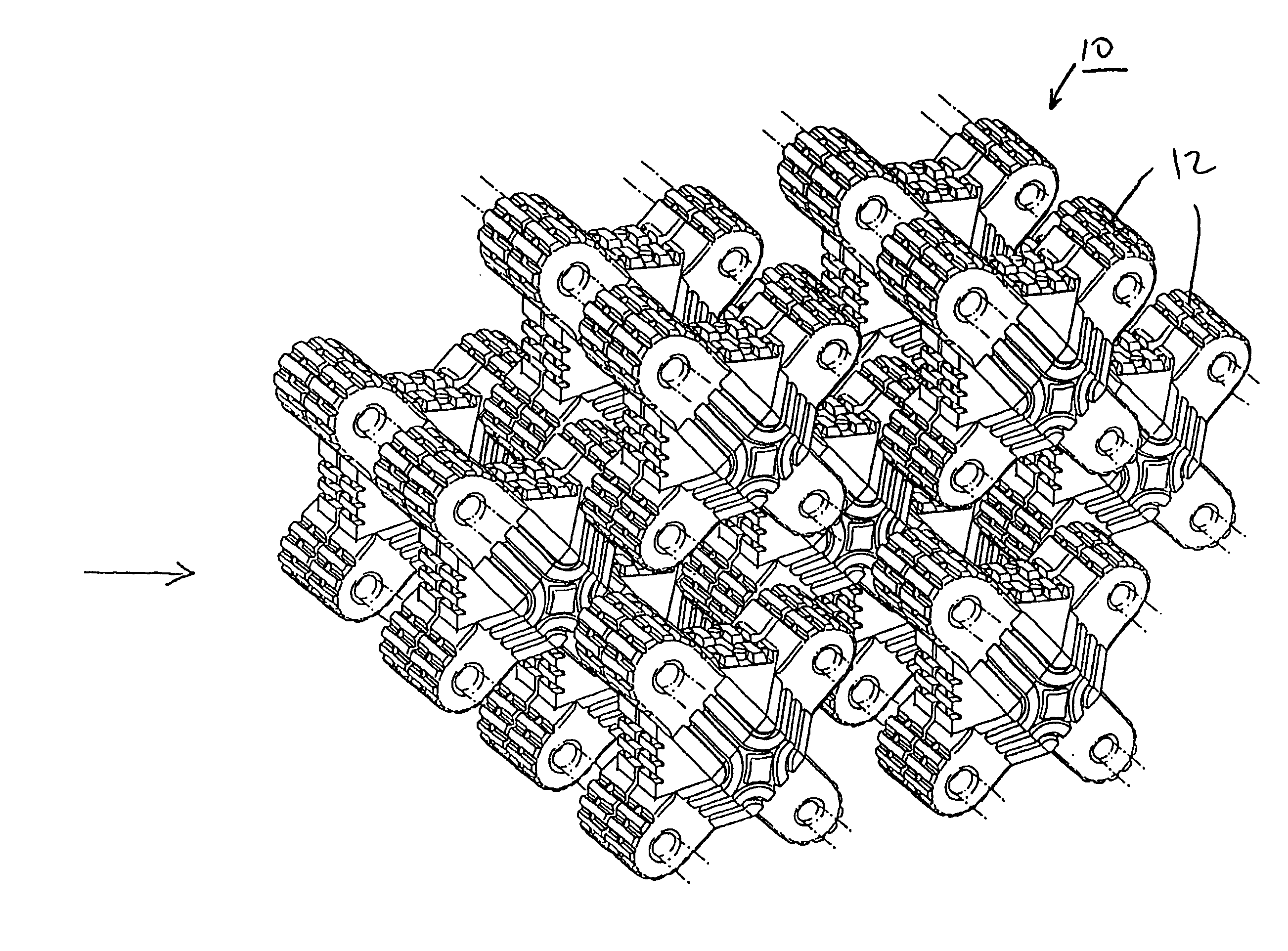
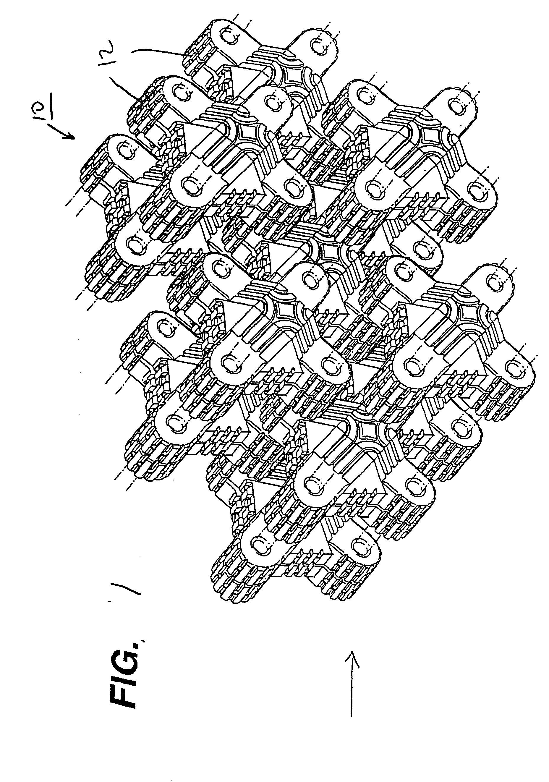
[0058] Referring to FIG. 1, a ribbed energy extraction system 10 (hereinafter the “system”) of the present invention is constructed and arranged for use offshore in the sea and oceans, as well as for use in the waters surrounding marinas, harbors and the like. Although the system has been characterized for use in particular with ocean waves, it is constructed and arranged to extract energy from flowing water, regardless of the salinity of water in which the system is positioned. In addition, as has been presented in the objects above, one of the advantages of the system is that it can be tuned to effectively and efficiently extract energy from flowing water, regardless of whether that water is flowing in the ocean, a delta or a river.

[0059] In FIG. 1, a portion of the system is shown including a plurality of pairs of ribbed modules 12 to be secured in a layered arrangement, an anchoring assembly, a restraining assembly, or other shapes to be disposed in the water to extract energy ...


PUM


Abstract

A ribbed module is provided having a ribbed exterior surface defining a plurality of grooves and channels along the surface for receiving water and directing the water in a direction different from that in which it is received to reduce wave energy. The module is formed as a single integral unit, or as a pair of halves having complementary mating locking elements which when engaged join the halves to form the ribbed module. A buoyancy system is also included to adjust the buoyancy of the module for positioning of same at a select position in the water. A plurality of modules are connected to provide breakwaters which reduce the effects of wave action on the shore.

Description

CROSS REFERENCE TO RELATED APPLICATIONS [0001] This application is a continuation-in-part of U.S. application Ser. No. 29 / 132,444 filed Nov. 9, 2000, and claims the benefit of U.S. Provisional Application No. 60 / 259,368 filed Dec. 29, 2000.BACKGROUND OF THE INVENTION [0002] 1. Field of the Invention [0003] The present invention relates to apparatus and methods used to intercept waves and disperse the energy therein to thereby dissipate, if not eliminate, the wave action. [0004] 2. Description of the Related Art [0005] Structures are known to be positioned in marine environments to function as breakwaters to reduce the effects of wave action from the shore. Such devices are disclosed in the patents discussed below. [0006] The construction and arrangement of breakwaters to reduce erosion of shorelines has changed to include other than just concrete fixtures. For example, such devices and systems are disclosed in: Inventor(s)U.S. Pat. No.  527,513See et al.1,593,863Brasher3,373,821Sar...

Claims


Application Information

Patent Timeline
Patent Type & Authority Applications(United States)
IPC IPC(8): E02B3/06
CPCE02B3/062Y02A10/11
Inventor SMITH, DENNIS G.
Owner WAVE DISPERSION TECH
Learn More