
Adjustable device for slowing liquid sloshing in moon pool

An adjustable, liquid technology, applied in the field of devices for reducing liquid sloshing in the moonpool of drilling ships or drilling platforms, and devices for reducing the swaying of marine engineering structures, which can solve the problems of wasting moonpool space and affecting the propulsion efficiency of ships. , to extend the service life, improve the effect of reducing sway and wave, and the effect of convenient maintenance

Active Publication Date: 2018-04-17
JIANGSU UNIV OF SCI & TECH
View PDF7 Cites 0 Cited by
  • Summary
  • Abstract
  • Description
  • Claims
  • Application Information

AI Technical Summary

Problems solved by technology

To slow down the sway of structures and the impact of seawater on the deck, the structure of the moon pool will also affect the propulsion efficiency of the ship
The existing moon pool sway reduction measures have changed the form of the moon pool, such as turning the corners of the rectangular moon pool into triangles or rounded corners. This structure can increase the strength of the moon pool, but it will not suppress the waves in the moon pool. Climbing will not prevent the front and rear encounters of the fluid in the moon pool to cause resonance, and at the same time waste a lot of space in the moon pool

Method used


Image

  • Adjustable device for slowing liquid sloshing in moon pool
  • Adjustable device for slowing liquid sloshing in moon pool
  • Adjustable device for slowing liquid sloshing in moon pool

Examples


Embodiment 1

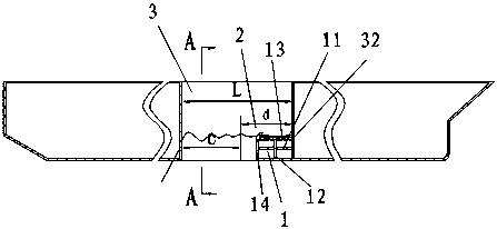
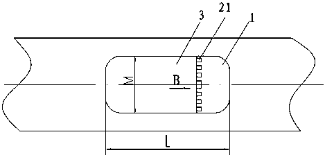
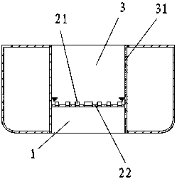
[0029] Such as Figure 1 to Figure 5 As shown, this embodiment includes a choke block 1 fixed on the lower part of the transverse wall plate 32 at the right end of the moon pool 3 and a wave dissipation mechanism 2 arranged at the upper outer corner of the choke block 1, and the choke block 1 is a rectangular parallelepiped shell structure, the housing is provided with horizontal ribs 11 and vertical ribs 12 supporting the housing to improve the strength of the choke block 1 . The wave breaking mechanism 2 includes a plurality of detachable baffles 21 and a central axis tube 22, the bottom of the detachable baffles 21 are embedded in the central axis tube 22 at intervals, and the middle part of the central axis tube 22 is fixed on the horizontal plate of the choke block 1 13 and the vertical plate 14, and the two ends of the central axis tube 22 are respectively welded and fixed on the longitudinal wall plates 31 on both sides of the moon pool 3. The bottom of the detachable ...

Embodiment 2

[0032] Such as Figure 6As shown, the structure of the wave elimination mechanism 2 of this embodiment is basically the same as that of Embodiment 1, the difference is that a plurality of circular holes 131 are respectively opened on the upper plate 13 and the vertical plate 14 of the choke block 1, and the circular holes 131 are respectively opened. The sum of the areas of the holes 131 accounts for 30% of the sum of the areas of the upper plate 13 and the vertical plate 14. The purpose of opening the holes is to make the fluid in the choke block 1 form a relatively independent and connected space. The fluid in this space helps to reduce the sloshing of the fluid in the moon pool 3, and at the same time helps to reduce the impact of the fluid on the choke block 1. impact effect.

Embodiment 3

[0034] Such as Figure 7 and Figure 8 As shown, the structure of the choke block 1 of this embodiment is the same as that of the second embodiment, and the wave breaking mechanism 2 is different from the first and second embodiments, which includes a wave breaking plate 201, a support shaft 202, two support shaft cylinders 203 and Two support bases 204, the left side of the wave breaking plate 201 is welded to the middle of the support shaft 202, the two ends of the support shaft 202 are respectively hinged to the support shaft tube 203, and one end of the support shaft tube 203 is respectively welded and fixed to the longitudinal walls on both sides of the moon pool 3 plate 31. The two ends of the wave breaking plate 201 respectively abut against the support seat 204 on the lower side thereof, the support seat 204 is in the shape of Π, and is respectively welded and fixed on the longitudinal wall plates 31 on both sides of the moon pool 3 . The included angle α between the...


PUM


Abstract

The invention discloses an adjustable device for reducing oscillation of liquid in a moon pool. The device comprises a flow stop block fixed to the lower portion of a transverse wall board at one end of the moon pool and a wave eliminating mechanism arranged at the outer corner of the top of the flow stop block, wherein multiple round holes are formed in the flow stop block. The wave eliminating mechanism comprises multiple detachable spoilers and a center shaft pipe, the bottoms of the detachable spoilers are embedded in the center shaft pipe at intervals, and the middle portion of the center shaft pipe is fixed to the joint of an upper flat board and a vertical board of the flow stop block. The bottoms of the detachable spoilers are cylindrically embedded in installation sections of the detachable spoilers, locating semi-cylinders are fixed into locating sections, and the end faces of the two ends of each locating semi-cylinder abut against the end face of the lower portion of the bottom of the corresponding detachable spoiler. According to another scheme, the wave eliminating mechanism comprises a wave eliminating board, a supporting shaft, two supporting shaft barrels and an open hole water pipe, or the wave eliminating mechanism is an independent open hole water pipe. By the adoption of the device, the structure is simple, an oscillation relieving effect on the liquid in the moon pool is remarkable, a wave eliminating effect is obvious, maintenance is convenient, and the work efficiency is greatly improved.

Description

technical field [0001] The invention relates to a device for reducing sloshing of marine engineering structures, in particular to a device for reducing liquid sloshing in a moon pool of a drilling ship or drilling platform, and belongs to the technical field of ships and marine engineering. Background technique [0002] With the depletion of land resources, the ocean has become another supply station for human resources, especially offshore oil is the key object of exploitation, and it is gradually shifting from shallow sea to deep sea. Various types of deep-sea drilling offshore engineering structures for exploiting marine energy continue to emerge, among which deep-sea drilling ships stand out because of their deep drilling waters and good flexibility. In order to ensure the stability of the drilling operation, the offshore engineering structure of the drilling is usually equipped with vertical through holes (moon pools) from the upper deck to the bottom at the front and b...

Claims


Application Information

Patent Timeline
Patent Type & Authority Patents(China)
IPC IPC(8): B63B1/40B63B35/44
CPCB63B1/40B63B35/4413Y02T70/10
Inventor 黄祥宏谷家扬蒋志勇姚震球
Owner JIANGSU UNIV OF SCI & TECH
Learn More