Re-transmitter and digital broadcast receiving system

a technology of retransmitter and receiving system, applied in the field of retransmitter and digital broadcast receiving system, can solve the problems of increasing the size of the retransmitter, affecting the quality of the retransmitter, and causing the error of receiving the signal

Inactive Publication Date: 2005-01-27
SANYO ELECTRIC CO LTD
View PDF30 Cites 10 Cited by
  • Summary
  • Abstract
  • Description
  • Claims
  • Application Information

AI Technical Summary

Benefits of technology

[0006] In order to solve the above-mentioned problem, a retransmitter according to the present invention is characterized by comprising a high-frequency input unit to which a receiving antenna for receiving a digital broadcasting wave is connected, a high-frequency output unit to which a retransmission antenna for retransmitting the digital broadcasting wave is connected, means for acquiring a frequency selection signal which is a signal fed from a digital broadcasting receiver and corresponds to indication as to which channel is selected by the digital broadcasting receiver, and selecting and feeding means for selecting, out of high-frequency signals inputted from the high-frequency input unit, the high-frequency signal having a frequency corresponding to the frequency selection signal and feeding the selected high frequency signal to the high-frequency output unit.

Problems solved by technology

However, it is expected that a receiving error occurs because a sufficient quality of a receiving signal is not obtained depending on the positional relationship among the indoor antenna, a window of a house, and a transmitting station.
When such retransmission is made, however, oscillation easily occurs by coupling an input and an output.
Therefore, the distance between a receiving antenna and a transmission antenna must be increased, thereby increasing the size of the retransmitter.
Consequently, the service information must be rewritten and retransmitted by the retransmitter, so that the configuration becomes complicated, resulting in increased cost.

Method used


Image

  • Re-transmitter and digital broadcast receiving system
  • Re-transmitter and digital broadcast receiving system
  • Re-transmitter and digital broadcast receiving system

Examples


Embodiment Construction

[0019] An embodiment of the present invention will be described on the basis of FIGS. 1 to 3.

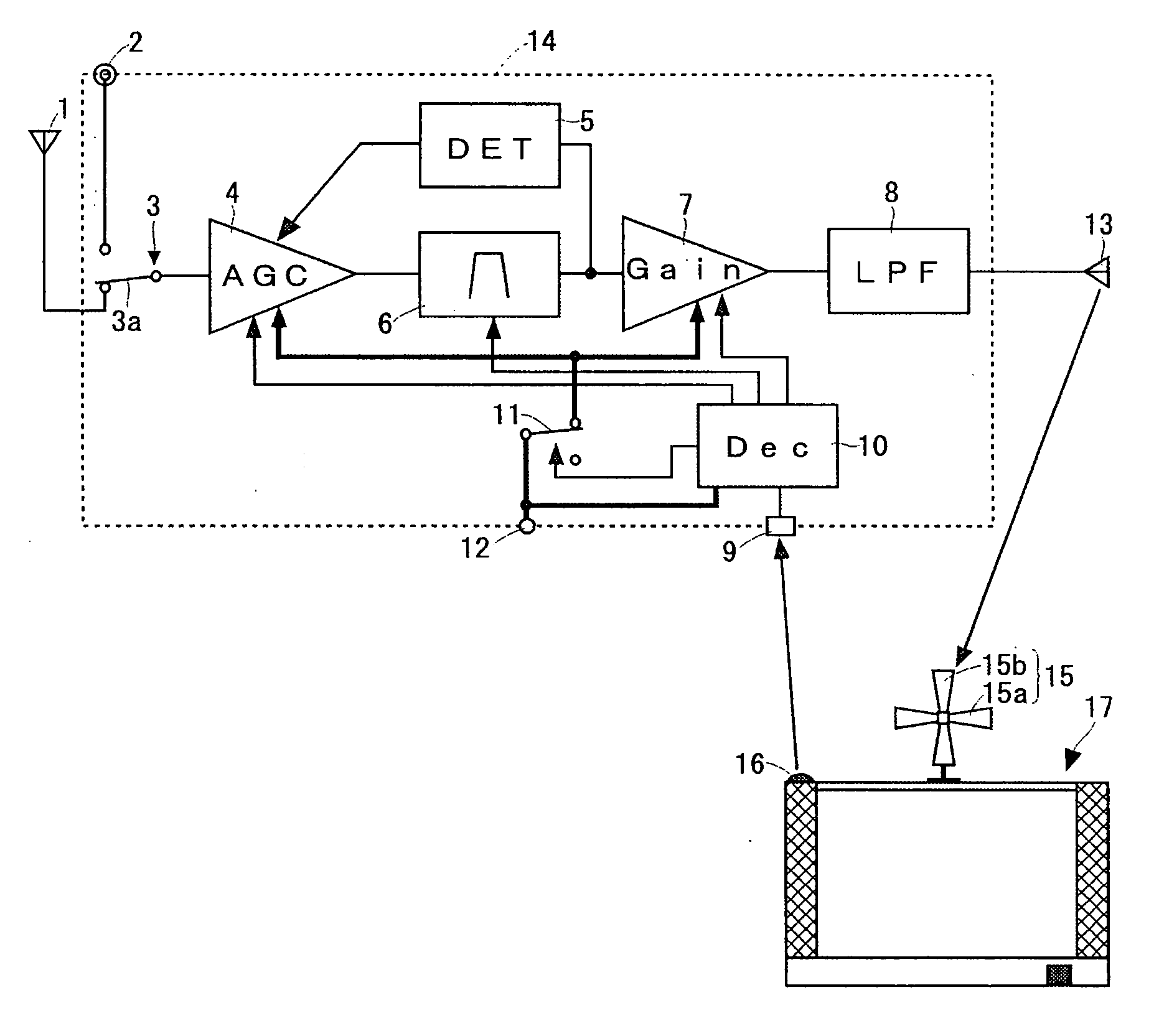
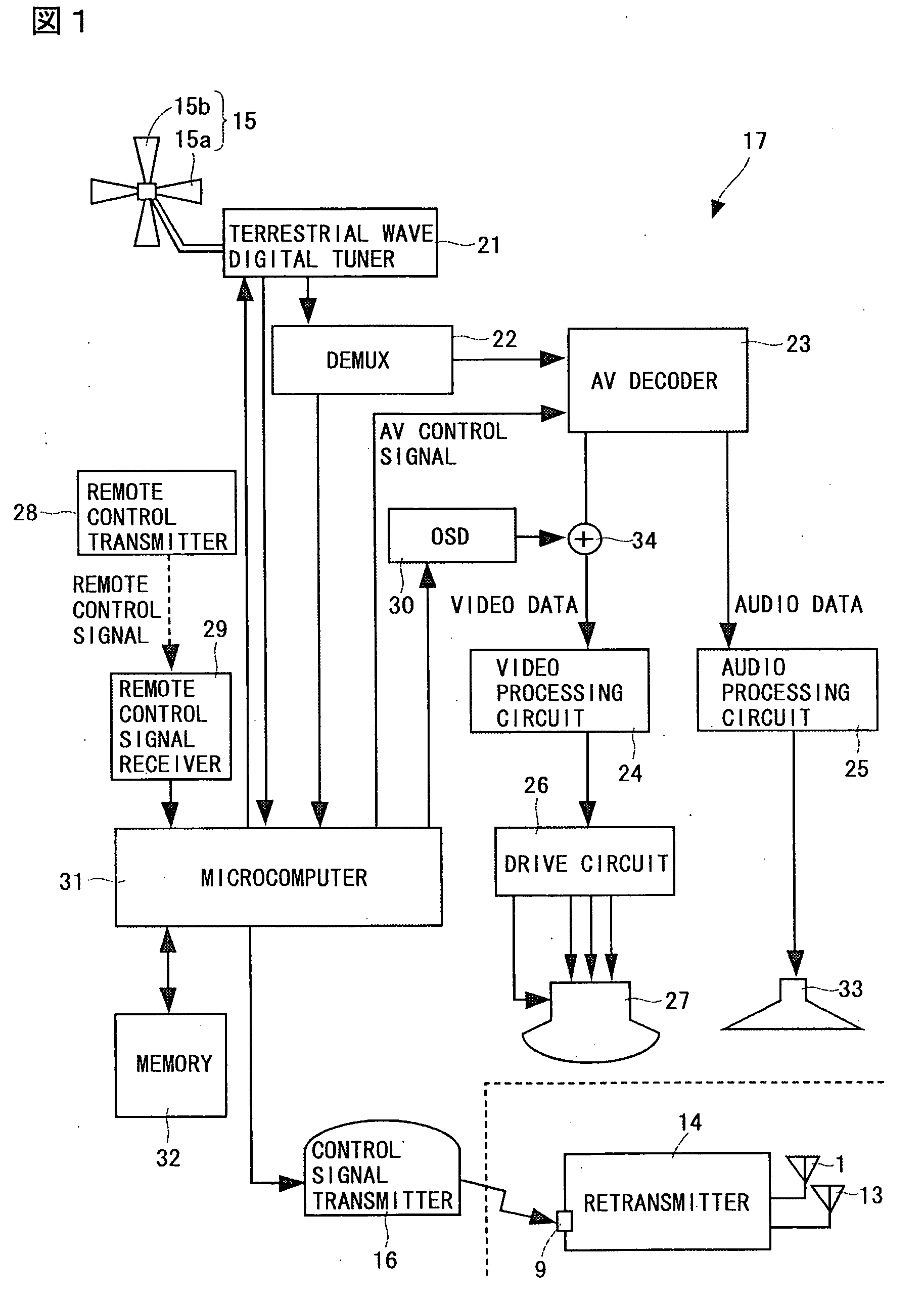
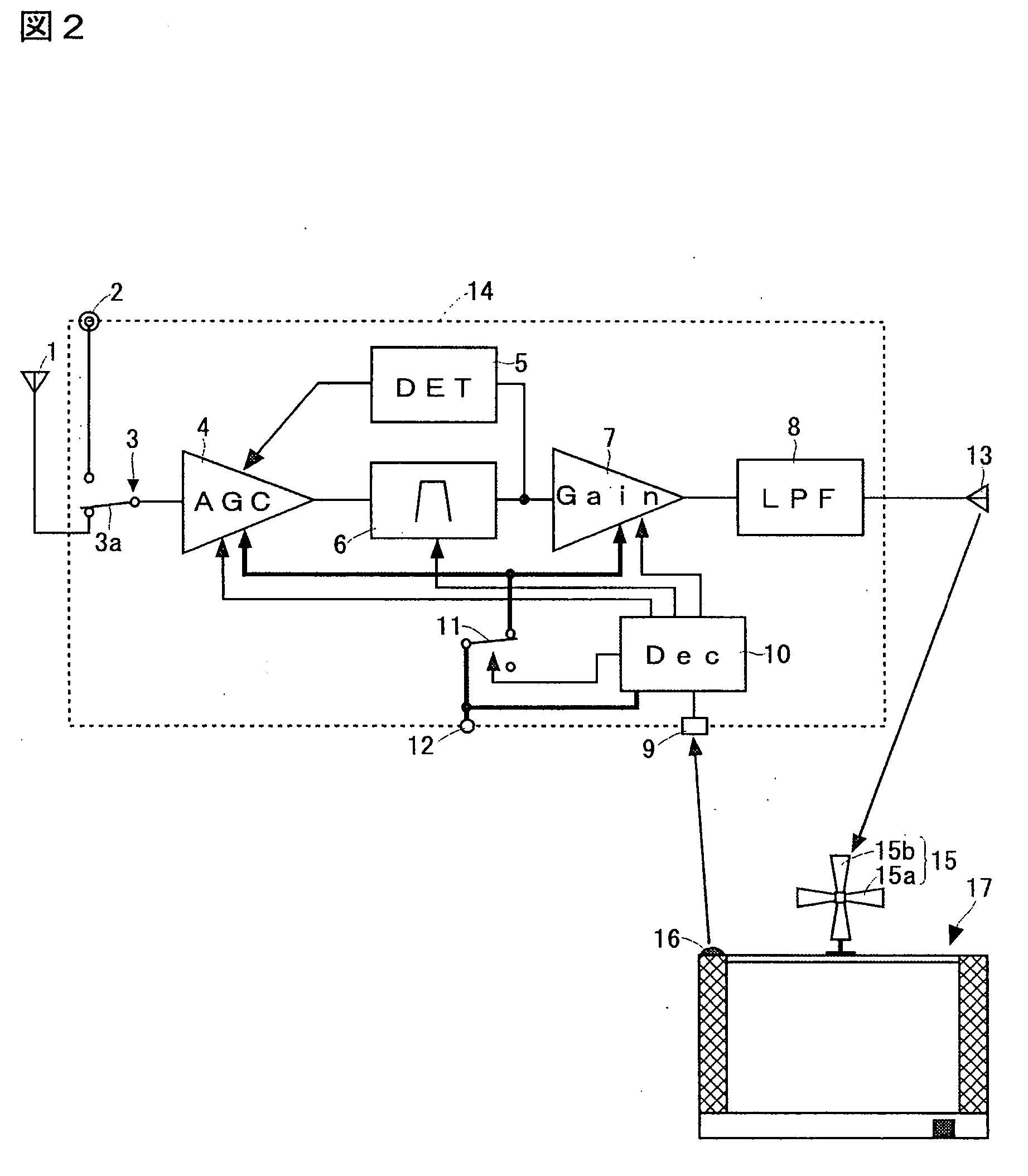
[0020] In FIG. 1, an indoor antenna 15 has a first receiving element 15a for receiving a digital broadcasting wave which is a horizontally polarized wave and a second receiving element 15b for receiving a digital broadcasting wave which is a vertically polarized wave. Processing for judging which of the elements feeds a receiving signal to be employed is performed by a terrestrial wave digital tuner 21 on the basis of a command from a microcomputer 31.

[0021] The terrestrial wave digital tuner 21 extracts, out of received high-frequency digital modulation signals (digital broadcasting waves), the digital modulation signal having a particular frequency. The terrestrial wave digital tuner 21 comprises a demodulation circuit, an inverse interleave circuit, an error correcting circuit, and so on, thereby demodulating the selected digital modulation signal to output a transport stream. Further, ...


PUM


Abstract

Information indicating which of channels is selected in a digital broadcasting receiver 17 is fed from a control signal transmitter 16 to a retransmitter 14. A terrestrial wave digital broadcasting wave from a transmitting station is inputted to a channel selection filter 6 through an indoor receiving antenna 1 and an automatic gain controller 4 in the retransmitter 14, and only a signal having a frequency component corresponding to the channel selected by the digital broadcasting receiver 17 is extracted, and is transmitted toward the digital broadcasting receiver 17 by a retransmission indoor antenna 13 through a variable gain amplifier 7.

Description

TECHNICAL FIELD [0001] The present invention relates to a retransmitter that receives digital broadcasting and retransmits the received digital broadcasting to a digital broadcasting receiver, and a digital broadcasting receiving system. BACKGROUND ART [0002] In a digital broadcasting system, a video / audio signal is compressed using a digital signal compression technique, and a stream (a transport stream) obtained by subjecting video / audio digital signals in a plurality of programs to time-division multiplexing is broadcast. On the other hand, a broadcasting receiver that receives such digital broadcasting selects one of a plurality of channels in digital broadcasting received through an antenna by a tuner, selects one of a plurality of programs included in the one channel by demultiplexing processing, and decodes a digital signal on the selected channel to output a video / audio signal. [0003] When terrestrial wave digital broadcasting is received, a usage way in which an indoor ante...

Claims


Application Information

Patent Timeline
Patent Type & Authority Applications(United States)
IPC IPC(8): H04B1/04H04B1/16H04B7/15H04N5/00H04N5/38H04N5/44H04N5/50
CPCH04N5/38H04N5/4401H04N21/4383H04N21/42204H04N21/43637H04N5/50H04N21/426H04N7/015
Inventor SHIBUSAWA, TORU
Owner SANYO ELECTRIC CO LTD
Why Eureka
Try Eureka