Reciprocating power tool

a power tool and counterweight technology, applied in the field of reciprocating power tools, can solve the problems of increasing the weight of the power tool itself by and achieve the effect of reducing the weight of the counterweight and reducing vibration

Active Publication Date: 2005-02-03
MAKITA CORP
View PDF21 Cites 25 Cited by
  • Summary
  • Abstract
  • Description
  • Claims
  • Application Information

AI Technical Summary

Benefits of technology

[0006] Accordingly, it is an object of the present invention to provide a useful technique for achiev

Problems solved by technology

However, the weight of the power tool itself is increased by the weight of the counter wei

Method used


Image

  • Reciprocating power tool
  • Reciprocating power tool
  • Reciprocating power tool

Examples


Embodiment Construction

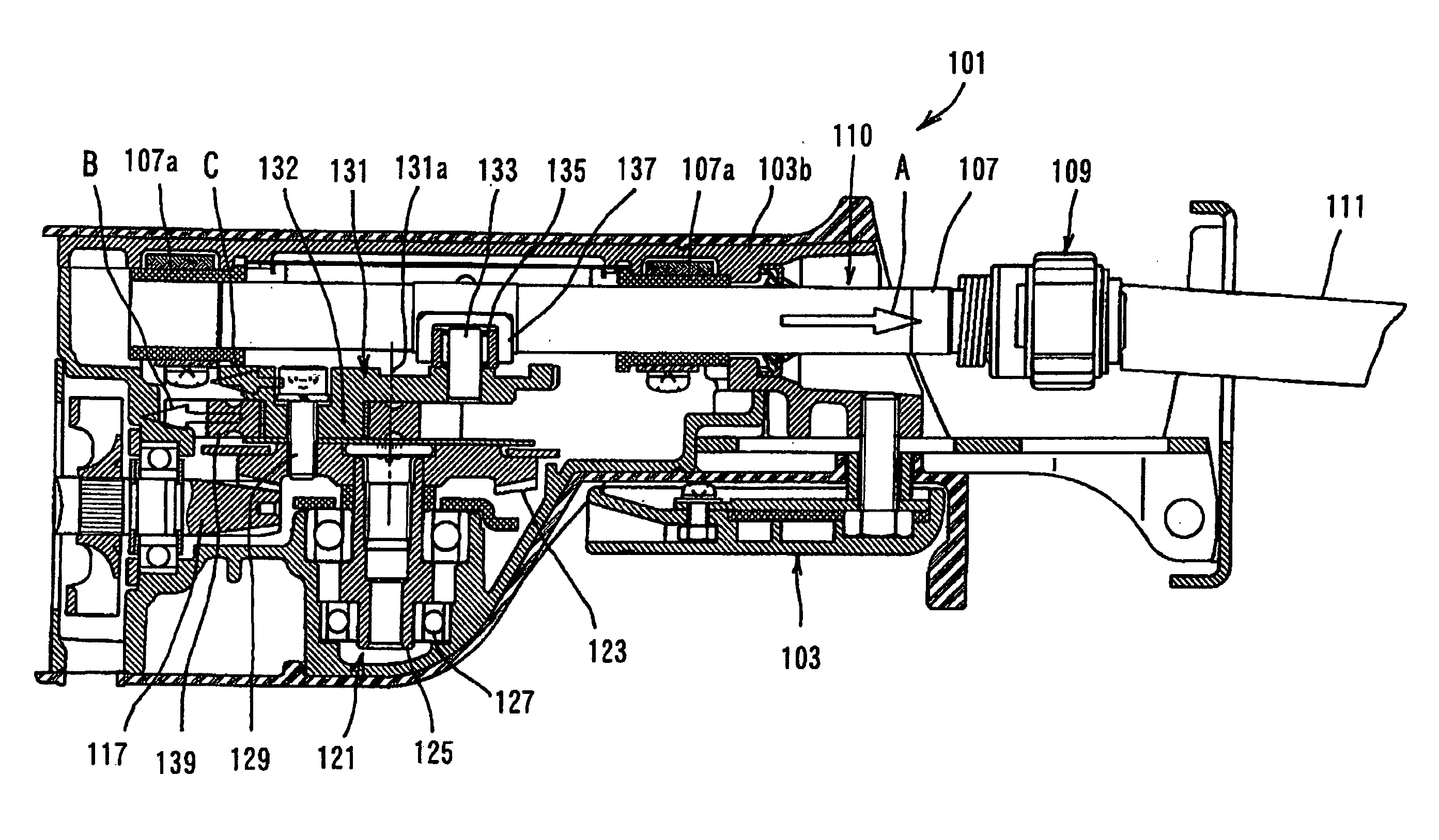
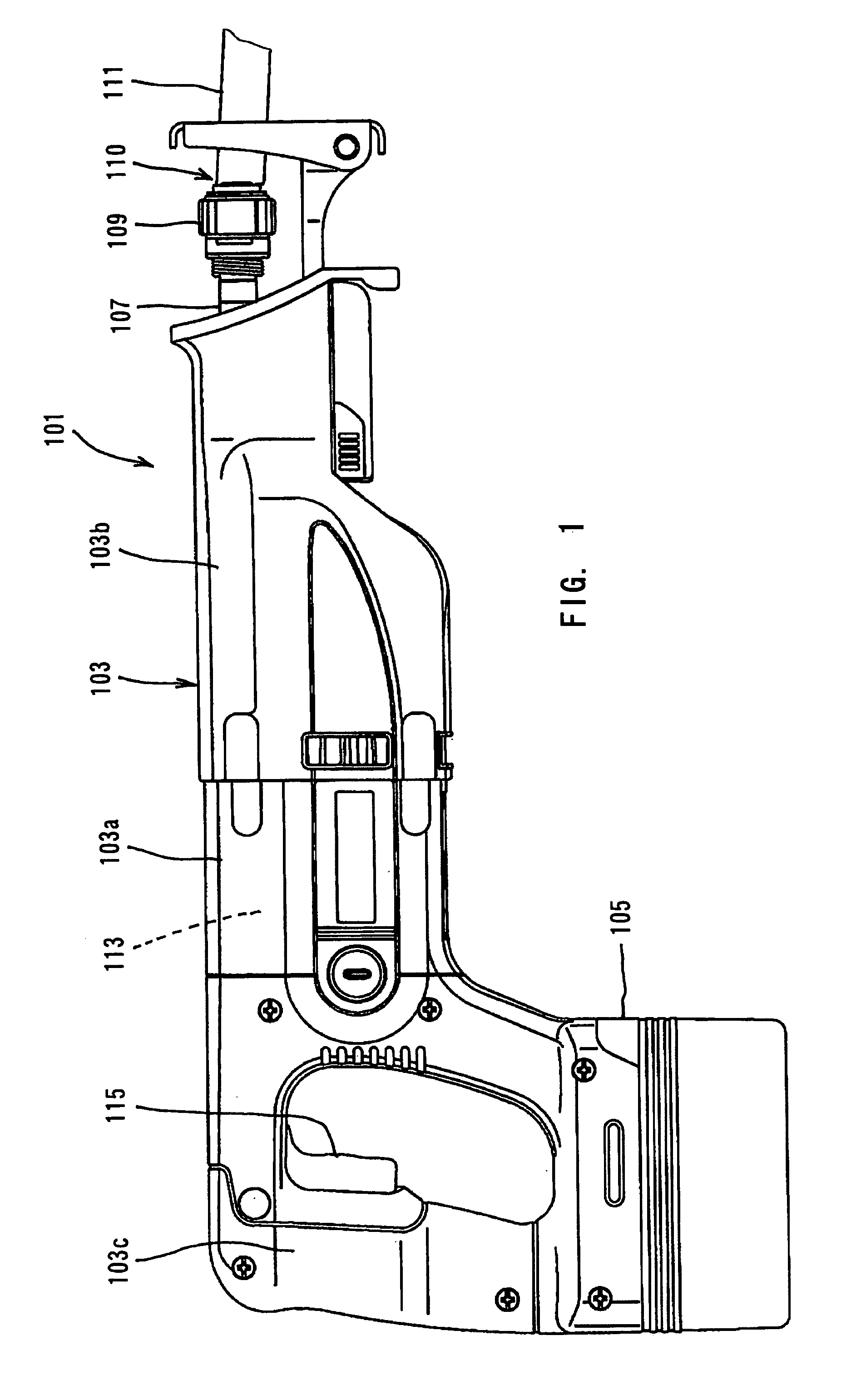
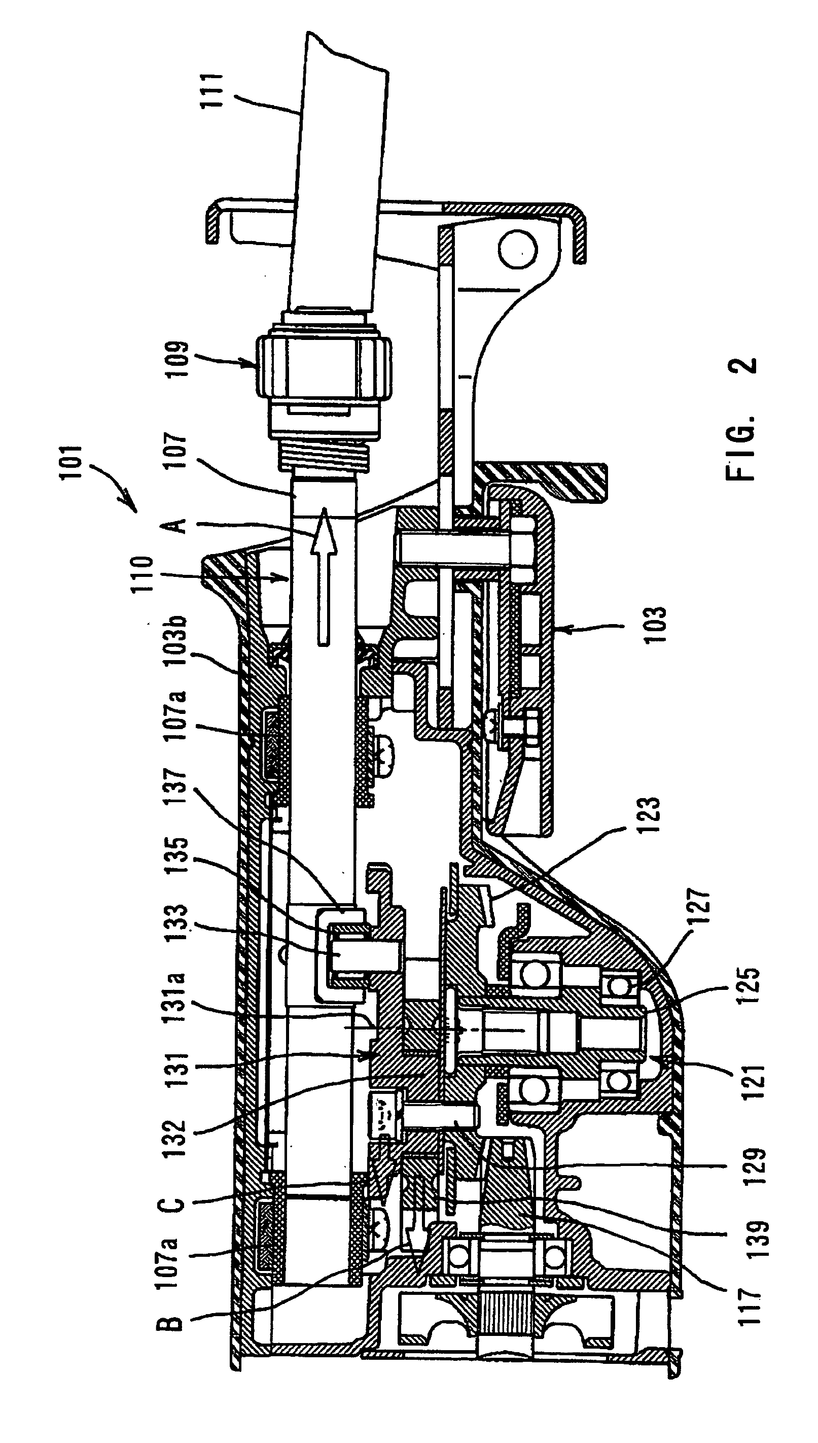
[0017] According to the present invention, a representative reciprocating power tool may include a motor, a tool bit, a slider, a motion converting mechanism, a counter weight and a component part of the motion converting mechanism. The reciprocating power tool according to the invention may include various power tools such as a reciprocating saw and a jig saw to be used to cut a work-piece of various materials such as wood, metal and stone.

[0018] Within the representative power tool, the tool bit performs a predetermined operation by reciprocating. The slider reciprocates to drive the tool bit. The motion converting mechanism converts a rotating output of the motor into a reciprocating movement of the slider.

[0019] Further, the counter weight reciprocates in a direction opposite to the reciprocating direction of the slider to reduce vibration caused by the reciprocating movement of the slider. The manner of “reciprocating in a direction opposite to the reciprocating direction of ...


PUM

PropertyMeasurementUnit
Weightaaaaaaaaaa
Thicknessaaaaaaaaaa
Gravityaaaaaaaaaa

Abstract

It is an object of the present invention to provide a useful technique for achieving weight reduction of the counter weight while reducing vibration in the reciprocating power tool. According to the invention, representative reciprocating power tool may include a motor, a tool bit, a slider, a motion converting mechanism, a counter weight and a component part of the motion converting mechanism. The tool bit performs a predetermined operation by reciprocating. The slider reciprocates to drive the tool bit. The motion converting mechanism converts a rotating output of the motor into a reciprocating movement of the slider. The counter weight reciprocates in a direction opposite to the reciprocating direction of the slider to reduce vibration caused by the reciprocating movement of the slider. The component part includes component of motion in a direction parallel to the reciprocating movement of the slider. The component part performs vibration reducing function together with the counter weight. Because component part can move parallel to the reciprocating slider to cooperate with the counter weight in reducing vibration caused within the power tool, the weight of the counter weight can be decreased while keeping the sufficient capability of vibration reducing function.

Description

BACKGROUND OF THE INVENTION [0001] 1. Field of the Invention [0002] The present invention relates to a reciprocating power tool such as a reciprocating saw and more particularly, to a technique of reducing vibration in actual operation of cutting a work-piece. [0003] 2. Description of the Related Art [0004] Japanese non-examined laid-open Patent Publication No. 2001-9632 discloses a reciprocating saw as an example of a reciprocating power tool. The known reciprocating saw includes a motion converting mechanism for causing a slider to reciprocate via the rotational movement of the motor. A tool bit is mounted on the end of the slider. Further, the motion converting mechanism has a counter weight. When the slider reciprocates, the counter weight reciprocates in a direction opposite to the reciprocating direction of the slider, or, with a 180° phase shift with respect to the slider. As a result, vibration caused by reciprocating movement of the slider can be reduced as much as possible...

Claims


Application Information

Patent Timeline
IPC IPC(8): B23D49/16B23D51/16
CPCB23D51/16Y10T74/18024Y10T74/18256Y10T74/18344Y10T83/8824Y10T83/8848
Inventor HIRABAYASHI, SHINJI
Owner MAKITA CORP
Why Eureka
Try Eureka