Method for detecting incipient position of meshing engagement between thread of vessel and thread of cap

a technology of meshing engagement and incipient position, which is applied in the field of capping methods and apparatus, can solve the problems of durability, threads on the cap and/or the vessel may be damaged,

Inactive Publication Date: 2005-02-03
SHIBUYA IND CO LTD
View PDF11 Cites 13 Cited by
  • Summary
  • Abstract
  • Description
  • Claims
  • Application Information

AI Technical Summary

Benefits of technology

[0016] With the described arrangement, the incipient position of a meshing engagement can be detected accurately, allowing the cap to be turned through a given angle of rotation as referenced to the incipient position, achieving a uniform clamping of caps to the vessels.

Problems solved by technology

According to the conventional method, the incipient position of a meshing engagement between both threads is determined on the basis of the magnitude of descent of the cap, and this, disadvantageously, requires the provision of means for detecting the descent.
Such detecting means would include a vertically slidable component, which undergoes an abrasion, thus presenting a problem in respect of durability.
A likelihood then arises that the threads on the cap and / or the vessel may be damaged.

Method used


Image

  • Method for detecting incipient position of meshing engagement between thread of vessel and thread of cap
  • Method for detecting incipient position of meshing engagement between thread of vessel and thread of cap
  • Method for detecting incipient position of meshing engagement between thread of vessel and thread of cap

Examples


first embodiment

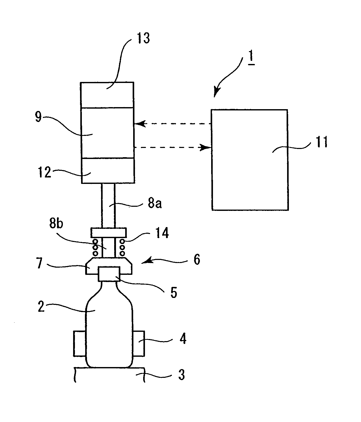
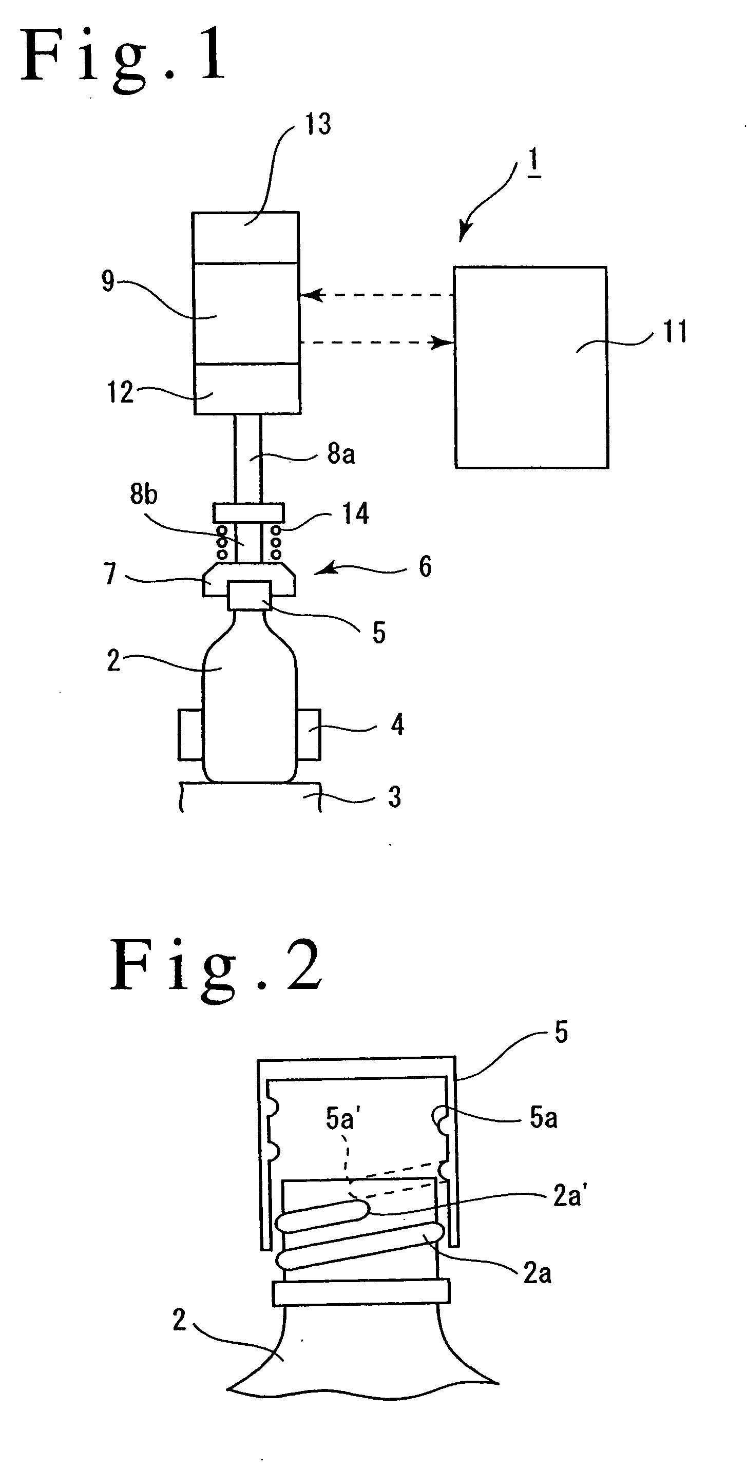
[0034] Referring to the drawings, several embodiments of the invention will now be described. A capping apparatus 1 includes a revolving body, not shown, which is rotatable in a horizontal plane. A plurality of receptacles 3 are disposed at an equal angular interval along the outer periphery of the revolving body, each receiving a vessel 2 thereon. A gripper 4 is associated with each receptacle 3 and is disposed on the revolving body to grip the barrel of the vessel 2. A capping head 6 is located above each receptacle 3 for holding a cap 5 for threadable engagement with the mouth of the vessel 2.

[0035] As shown in FIG. 2, on its outer peripheral surface, the mouth of the vessel 2 is formed with male threads 2a while the inner peripheral surface of the cap 5 is formed with female threads 5a.

[0036] The capping head 6 includes a chuck 7, which is known in itself, for detachably holding the cap 5 under pneumatic pressure, and a pair of upper and lower splined shafts 8a, 8b which are c...

second embodiment

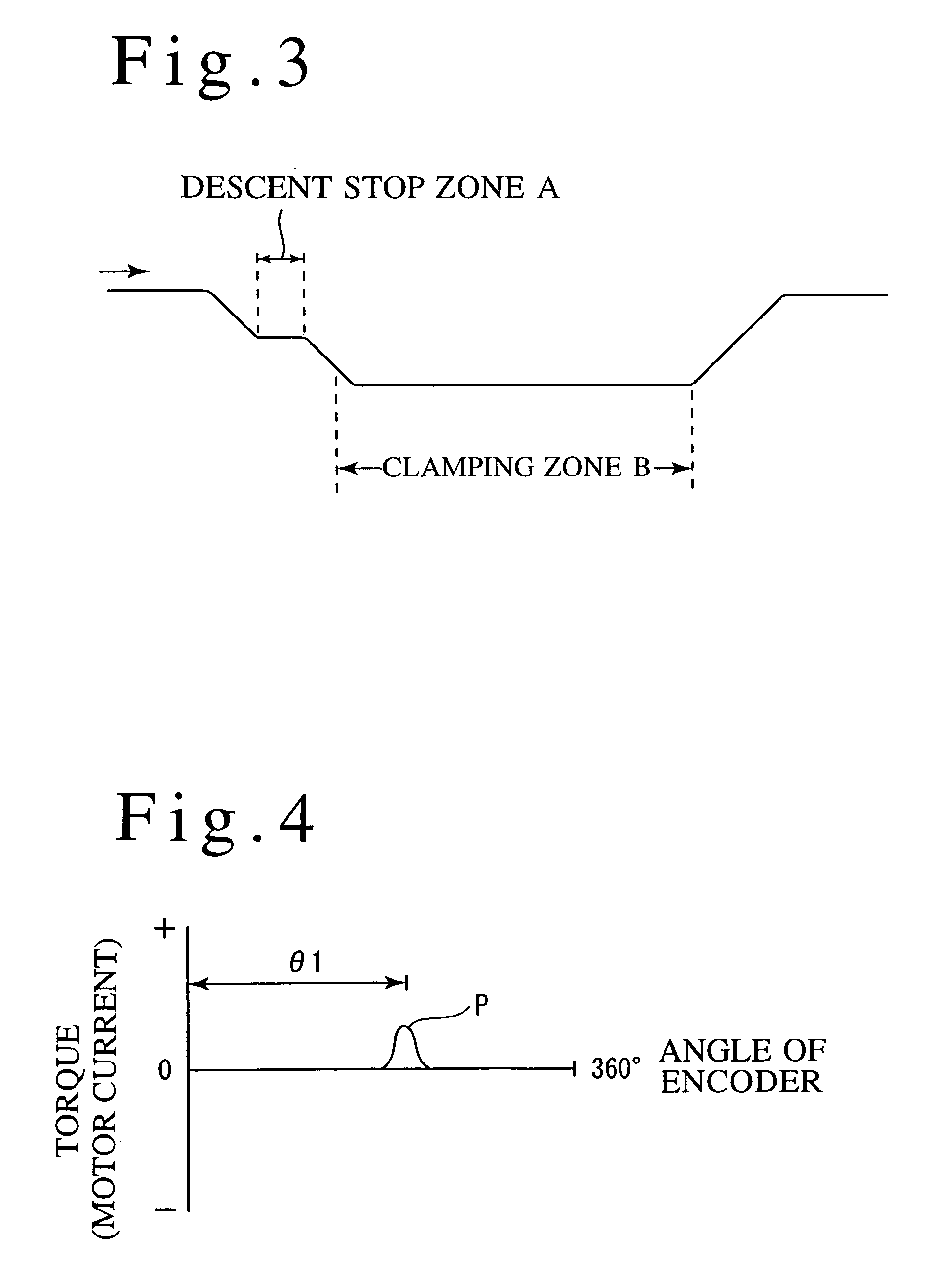
[0058] FIGS. 6 to 8 show a second embodiment of the invention. In this embodiment, there is provided a reverse zone A as shown in FIG. 7 where the controller 11 causes the motor 9 to be rotated through one revolution in a direction opposite from the clamping direction in a region where the elevating cam causes the capping head 6 to descend. In a reverse zone A, at least the lowest extremity 5a—of the female threads 5a on a cap 5 is enabled to abut against the top end 2a—of the male threads 2a on a vessel 2 (see left part of FIG. 6). In other words, the motor 9 is controlled so that in the course of descent of the capping head 6, the cap 5 is caused to rotate through one revolution in the reverse direction at the time when the lowest extremity 5a—of the female threads 5a on the cap 5 is located below the uppermost portion of the top end 2a—of the male threads 2a on the vessel 2.

[0059] When the cap 5 is rotated through one revolution in the reverse direction, as shown in FIG. 6, the ...

third embodiment

[0065] FIGS. 9 to 11 illustrate a third embodiment of the invention. In the third embodiment, there is provided a rapid rotation zone A where the cap 5 is rapidly rotated in the clamping direction, the rapid rotation zone A being provided in the course of descent of the capping head 6 which takes place under the influence of the elevating cam and before the capping head 6 descends to the clamping zone B. In the rapid rotation zone A, the controller 11 drives the motor 9 to cause the cap 5 to rotate in the clamping direction from a point in time when at least the lowest extremity 5a—of the female threads 5a on the cap 5 does not abut against the top end 2a—of the male threads 2a on the vessel 2.

[0066] At this time, a rotational speed of the motor 9 is chosen to be such that the cap rotates at least through one revolution during the time the cap 5 descends in the vertical direction by an amount corresponding to the width of a single one of the male threads 2a on the cap 2 under the i...


PUM

PropertyMeasurementUnit
torqueaaaaaaaaaa
angle of rotationaaaaaaaaaa
vertical distanceaaaaaaaaaa

Abstract

A capping apparatus 1 includes torque sensor 12 which detects an output torque when a chuck 7 is driven for rotation by a motor 9. Initially, a cap 5 is held by the chuck 7. The cap 5 is fitted over a mouth of a vessel 2, and then the chuck 7 is rotated through one revolution in a clamping direction. A resulting output torque is detected by the torque sensor 12, and the output torque rapidly increases at the position where the threads on the cap 5 and the vessel 2 abut against each other (an incipient position of meshing engagement P). The cap 5 is rotated through a given angle of rotation as referenced to the incipient position of meshing engagement P, thus threadably engaging the cap 5 with the vessel 2. The invention allows a uniform clamping of cap 5 at the completion of the capping operation.

Description

[0001] This is a continuation of Ser. No. 09 / 777,378, filed Feb. 6, 2001.FIELD OF THE INVENTION [0002] The present invention relates to a capping method and apparatus, and more particularly, a capping method and apparatus in which an incipient position of a meshing engagement between threads on a vessel and threads on a cap is detected and then the cap is turned through a given angle of rotation as referenced to the detected position to clamp the cap onto the vessel. DESCRIPTION OF THE PRIOR ART [0003] A capping method of the kind described is known in the art (see for example, Japanese Patent Publication No. 86,034 / 1995 and Japanese Laid-Open Patent Application No. 124,196 / 1999). [0004] In the disclosed method, the incipient position of a meshing engagement between the threads on the vessel and the threads on the cap is detected by initially fitting the cap over the threads on the vessel from above and turning the cap in a direction opposite from the direction in which it is clampe...

Claims


Application Information

Patent Timeline
Patent Type & Authority Applications(United States)
IPC IPC(8): B67B3/20B67B3/26G01L5/00
CPCB67B3/20B67B3/206B67B3/264B67B3/26B67B3/2093
Inventor KITAMOTO, HIROAKI
Owner SHIBUYA IND CO LTD
Why Eureka
Try Eureka