Electrostatic coating apparatus

a coating apparatus and electrostatic technology, applied in the direction of electrostatic spraying apparatus, coating, spraying apparatus, etc., can solve the problems of unevenness and imperfections in the coating

Inactive Publication Date: 2005-02-03
NISSHINBO IND INC
View PDF3 Cites 4 Cited by
  • Summary
  • Abstract
  • Description
  • Claims
  • Application Information

AI Technical Summary

Benefits of technology

[0014] The present invention is conceived in light of the foregoing drawback of the conventional art, and has as an object to provide an improved electrostatic coating apparatus in which lumps of coating particles do not fall onto the back plate and cause unevenness and imperfections in the coating.
[0021] According to the invention described above, when the charged coating particles are discharged from the plurality of nozzles toward the work piece, the coating particles adhere to the surface of the work piece to form a layer of coating particles. The coating particles that do not adhere to the work piece fall onto the surface of the conveyer belt on which the work piece rests, adhere to the connecting member supporting the nozzles, and so forth. The attachment surface of the connecting member is a smooth surface, however, and therefore the coating particles adhere to the surface evenly, without concentrating locally into icicles. Since icicles do not form, lumps of coating particles do not fall onto the work piece or conveyor belt, and therefore unevenness and imperfections in the coating can be prevented.
[0022] If the smooth surface of the connecting member is inwardly concave, the work piece can be enclosed from all sides within a single unit and the occurrence of icicles can be prevented.
[0024] As described above, the present invention, in an electrostatic coating apparatus provided with a plurality of nozzles that spray electrostatically charged coating particles, connects the nozzles with least one connecting member, with the surface of the openings at the tips of the nozzles disposed within a smooth surface of the connecting member. As a result, when the charged coating particles are discharged from the nozzles, the present invention prevents the formation of icicles of coating particles even if excess coating particles adhere to the surface of the connecting member, and thus can prevent unevenness and imperfections in the coating.

Problems solved by technology

These icicles of coating particles fall off when they attain a certain length, with the resulting lumps of coating particles adhering to the back plate 11 and causing unevenness and imperfections in the coating.

Method used


Image

  • Electrostatic coating apparatus
  • Electrostatic coating apparatus
  • Electrostatic coating apparatus

Examples


Embodiment Construction

[0033] Preferred embodiments of the present invention are now described in detail in accordance with the accompanying drawings.

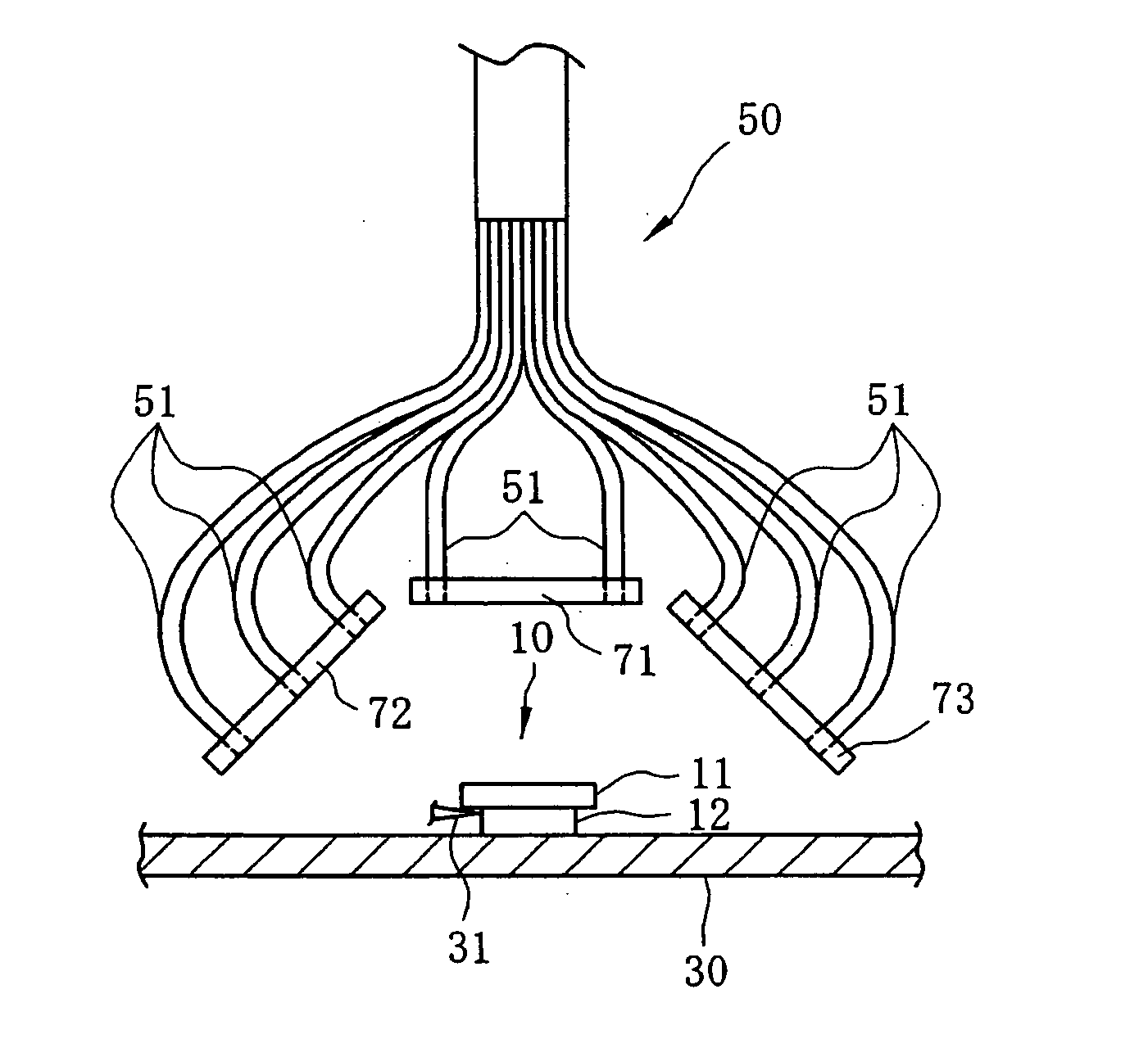
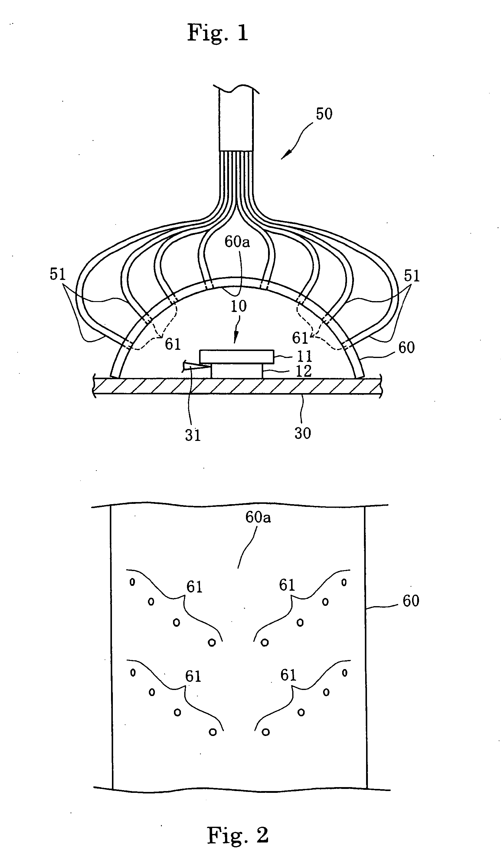
[0034]FIG. 1 is a diagram showing a front view of the main parts of an electrostatic coating apparatus in the present invention.

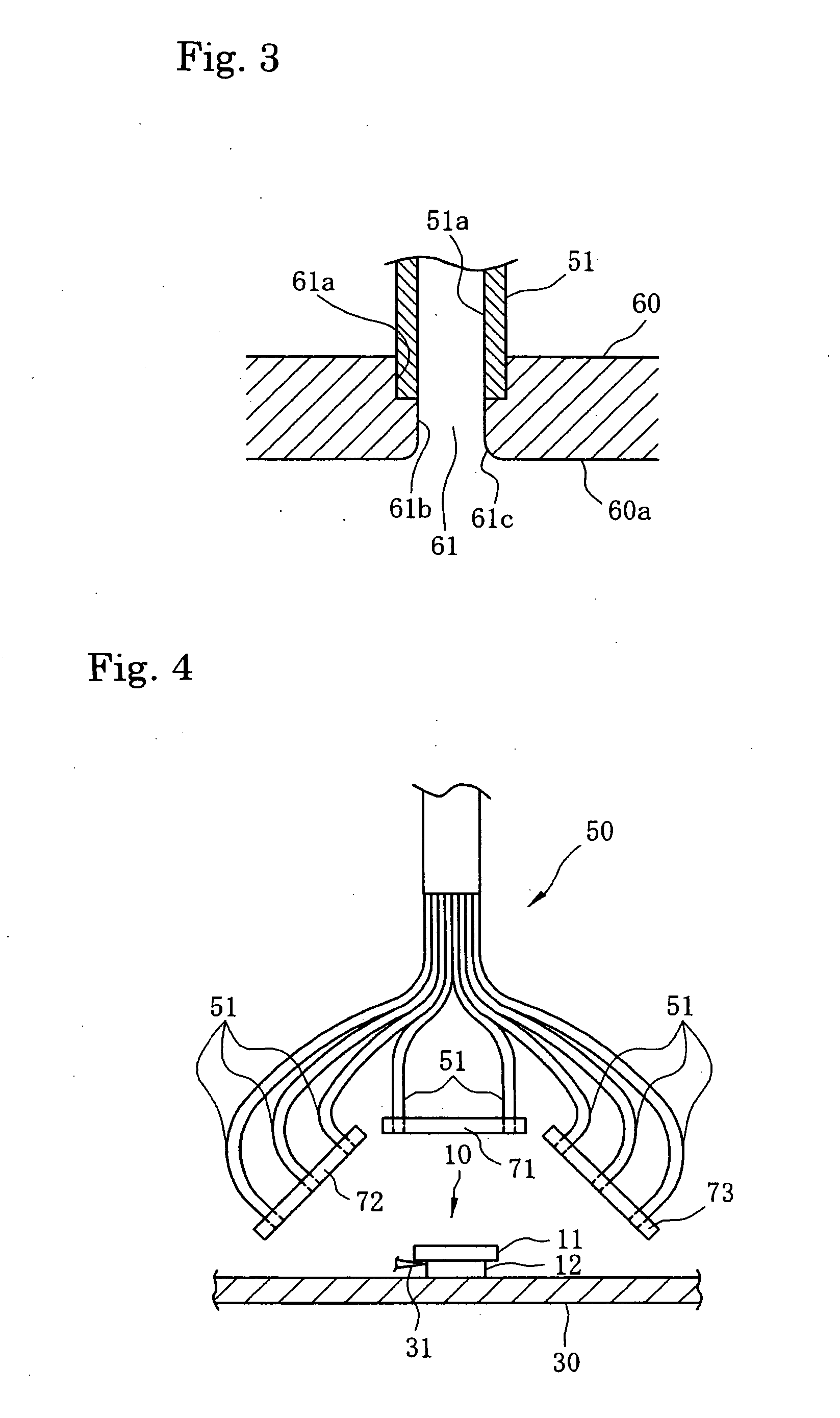
[0035] As shown in FIG. 1, a conveyor belt 30 is disposed so as to convey a work piece through a coating chamber, not shown. Preferably, the conveyor belt 30, which may be made of urethane or some other suitable material, is not electrically conductive, in order to facilitate the collection for reuse of coating particles. A disk pad 10 is set on the conveyor belt 30 so that friction material 12 faces down.

[0036] A coating apparatus 50 is mounted on a roof of the coating chamber. A plurality of nozzles 51 that spray coating particles is disposed along both sides of the coating apparatus 50. Preferably, the nozzles 51 are made of a non-conductive material, which may be polyvinyl chloride or some other, suitable material. As in the ...


PUM


Abstract

The present invention provides an improved electrostatic coating apparatus that prevents imperfections in coating due to lumps of coating particles falling on the work piece. The electrostatic coating apparatus, which has multiple nozzles that spray electrically charged coating particles, has least one connecting member that connects the nozzles to each other, in such a way that the surface of the opening at the tip of the nozzle is inserted in a smooth interior surface of the connecting member. Although some of the coating particles discharged from the nozzles adhere to the interior surface, because the surface is smooth the coating particles can be prevented from concentrating locally into icicles that might fall onto the work piece.

Description

CLAIM OF PRIORITY [0001] This application claims priority from Japanese Patent Application No. 2003-271228, entitled “Electrostatic Coating Apparatus” filed on Jul. 7, 2003, the entire contents of which are incorporated herein by reference. FIELD OF THE INVENTION [0002] The present invention relates to an improved electrostatic coating apparatus, and more particularly, to an electrostatic coating apparatus that prevents drops of paint from forming icicles around the nozzles of the apparatus so as to prevent uneven coating of a work piece. BACKGROUND OF THE INVENTION [0003]FIGS. 5A, 5B and 5C are diagrams showing plan, lateral and bottom views of a conventional disk pad, respectively. [0004] A disk pad, used as a friction member in disk brakes and the like, as shown in FIGS. 5A, 5B and 5C, is composed of a back plate 11 and a friction material 12. The back plate 11 is a plate made of a metal such as steel. In the example shown in the diagrams, two projections are provided at the top ...

Claims


Application Information

Patent Timeline
Patent Type & Authority Applications(United States)
IPC IPC(8): B05B1/14B05B5/025B05B5/08
CPCB05B1/14B05B5/084B05B5/08B05B5/025
Inventor ISHII, YASUJIIMAI, JUNICHI
Owner NISSHINBO IND INC
Why Eureka
Try Eureka