Apparatus and method for monitoring supplemental oxygen usage

a technology of supplemental oxygen and apparatus, which is applied in the direction of respirators, operating means/release devices of valves, underwater equipment, etc., can solve the problems of unnecessarily high oxygen consumption, severe limitation of mobile time, and continuous oxygen flow

Inactive Publication Date: 2005-02-03
SUNRISE MEDICAL HHC INC
View PDF11 Cites 18 Cited by
  • Summary
  • Abstract
  • Description
  • Claims
  • Application Information

AI Technical Summary

Problems solved by technology

The difficulty with the basic system is that the oxygen flow must be continuous.
This results in an unnecessarily high oxygen consumption.
Either the mobile tim

Method used


Image

  • Apparatus and method for monitoring supplemental oxygen usage
  • Apparatus and method for monitoring supplemental oxygen usage
  • Apparatus and method for monitoring supplemental oxygen usage

Examples


Embodiment Construction

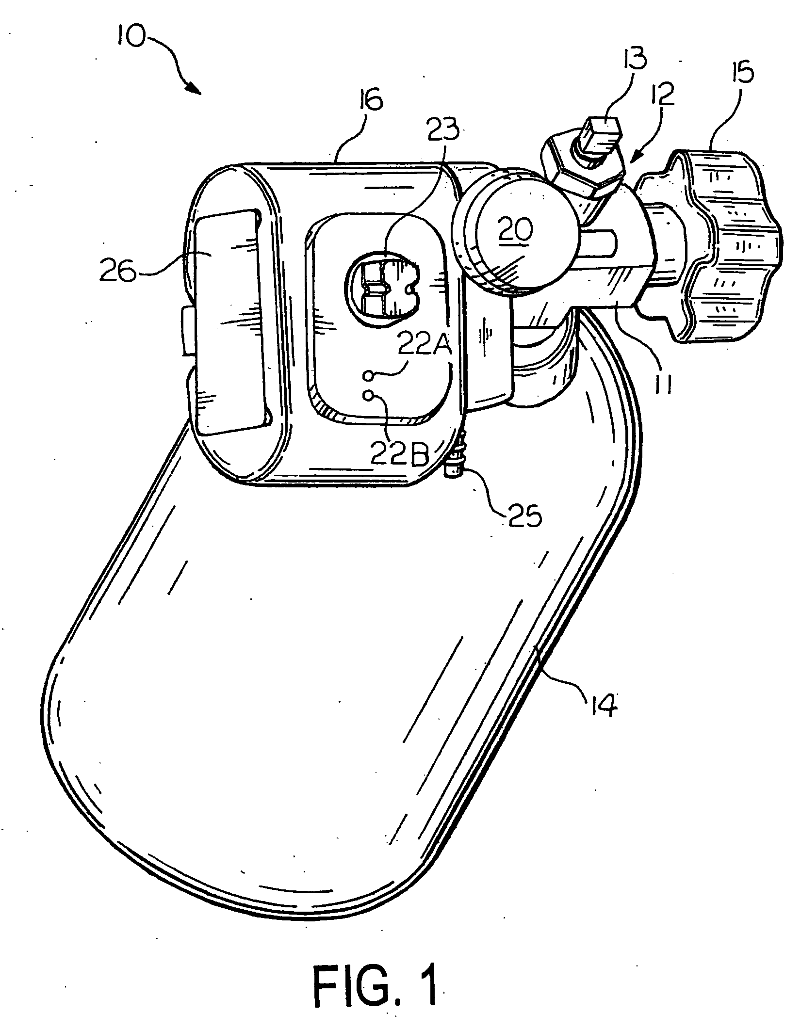
[0013] Referring now to the drawings, FIG. 1 shows a gas management device 10 in accordance with the present invention. The gas management device 10 has a regulator base 11 with a center opening 12 which is configured to fit over a post 13 of an gas cylinder 14. In the preferred embodiment, the cylinder 14 contains pressurized oxygen; however, the cylinder 14 also may be a liquid oxygen reservoir. A round handle 15 projects from the regulator base 11 and may be manually rotated for releasably securing the device 10 to the gas cylinder 14. It will be appreciated that other handle shapes also may be provided.

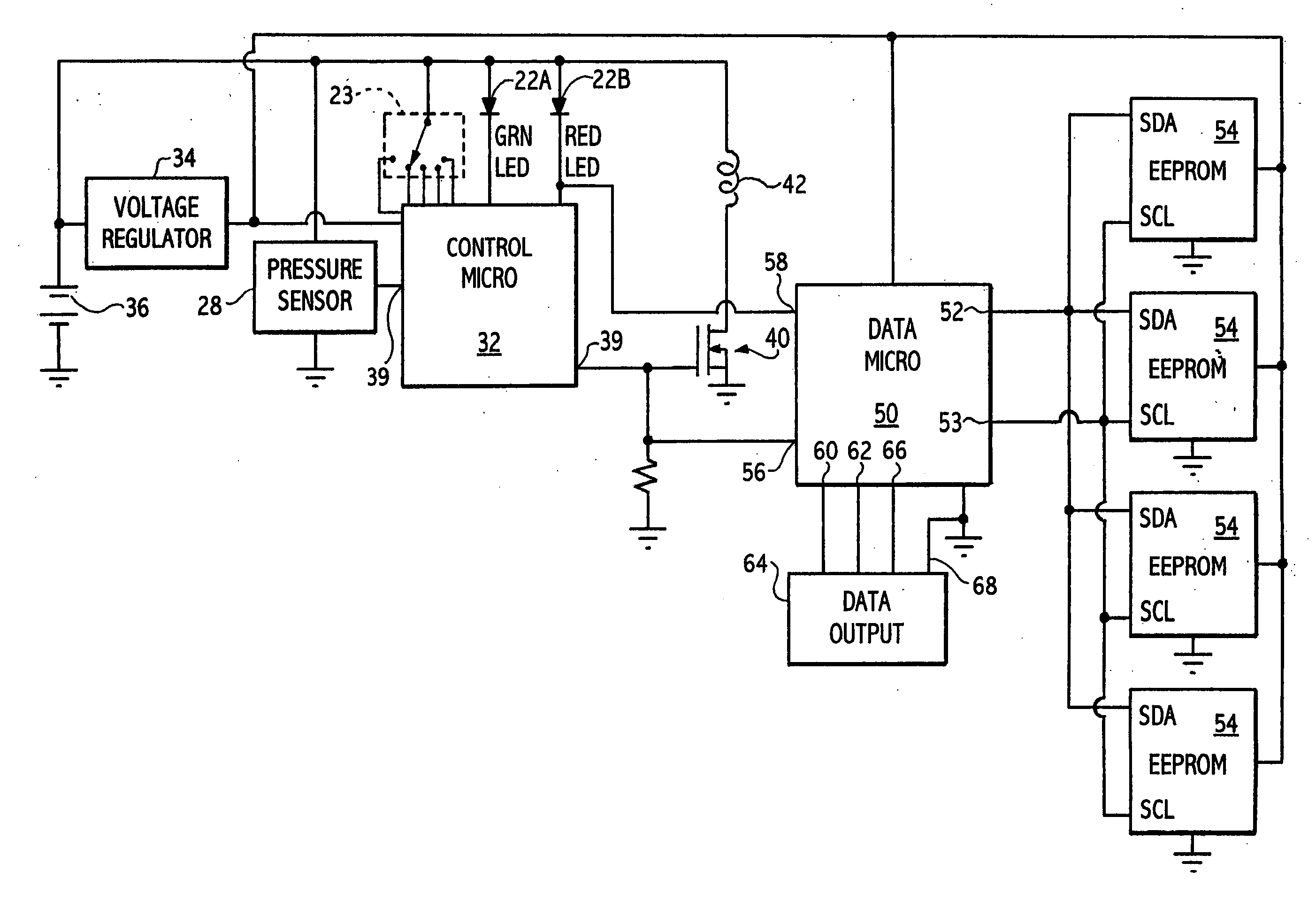
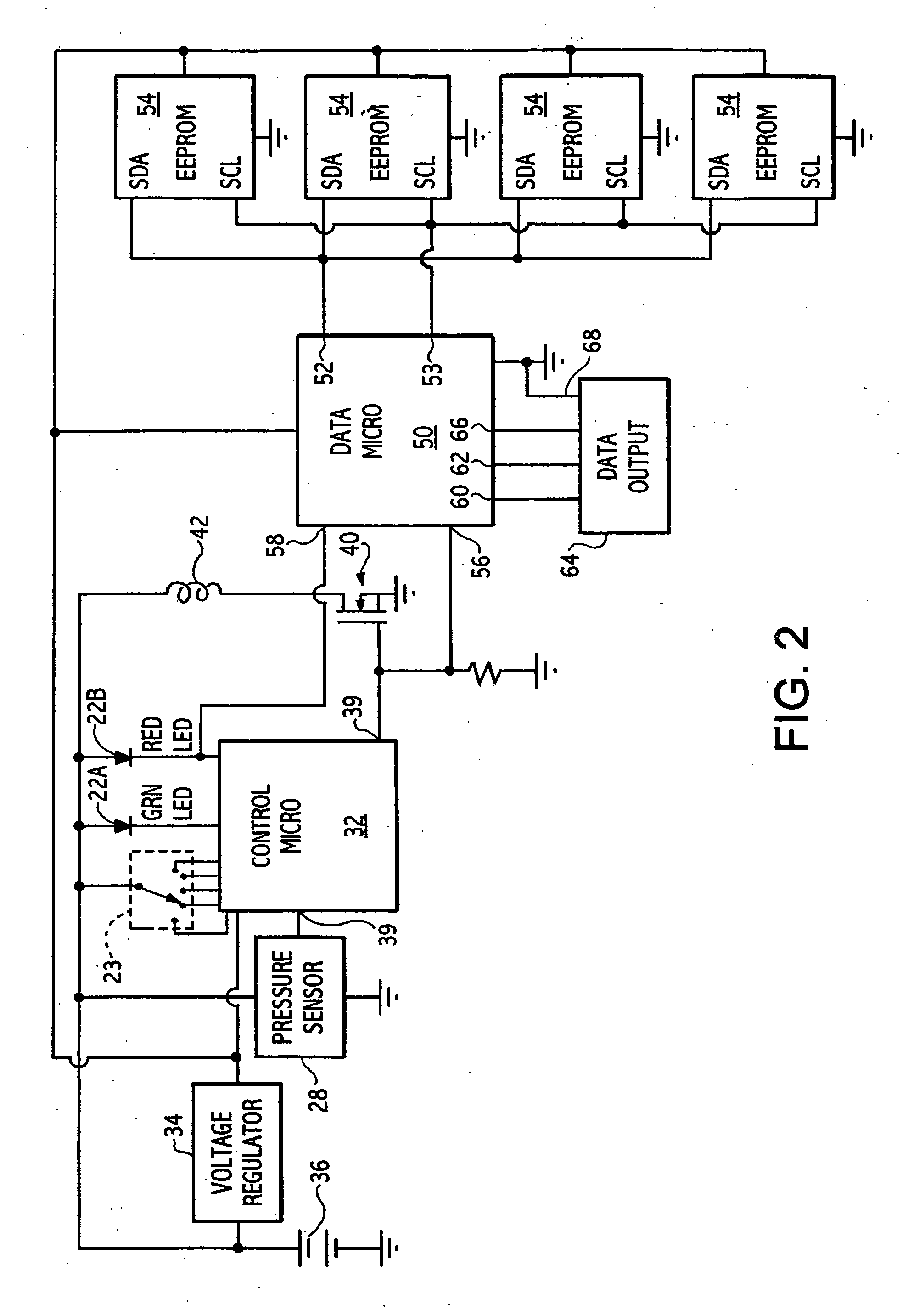
[0014] The components of the gas management device 10 are contained within a housing 16. As shown in FIG. 1, several indicating devices are located upon the surface of the housing 16. These may include a pressure gauge 20 and a pair of LED indicators 22A and 22B. The indicating LEDs 22A and 22B will be discussed in detail below. In addition, a mode selection switch 23 for selecti...


PUM


Abstract

A device for monitoring and recording the usage of gas supply apparatus. The device includes erasable memory for storing the usage data and a connection for periodically downloading the data to a personal computer.

Description

CROSS REFERENCE TO RELATED APPLICATIONS [0001] This application claims the benefit of Provisional Patent Application Ser. No. 60 / 482,356 filed Jun. 25, 2003.BACKGROUND OF INVENTION [0002] This invention relates in general to devices for mounting upon a compressed oxygen cylinder or liquid oxygen reservoir for controlling the delivery of supplemental oxygen to an ambulatory patient and in particular to an apparatus and method for monitoring the operation of the device. [0003] As the number of aged people in the population increases, there is an increasing number of people who require supplemental oxygen therapy. Many of these people are ambulatory and are capable of leaving the home and hospital. However, they require a portable source of supplemental oxygen in order to remain mobile. In the most basic supplemental oxygen system, compressed oxygen from a tank is supplied to the ambulatory patient through a pressure reducing regulator and a tube connected to a nasal cannula. The diffi...

Claims


Application Information

Patent Timeline
IPC IPC(8): A61MA61M16/00A61M16/06A61M16/10A62B7/00
CPCA61M16/10A61M2016/0021A61M2016/0027A61M16/0677A61M2205/35A61M2205/52A61M2205/8212A61M2202/0208A61M2202/03A61M2202/0007A61M16/00B63C11/22
Inventor FROLA, FRANK R.
Owner SUNRISE MEDICAL HHC INC
Why Eureka
Try Eureka