
Pass through sliding drapery suspension system

Inactive Publication Date: 2005-02-03
PUTMAN MICHAEL
View PDF28 Cites 22 Cited by
  • Summary
  • Abstract
  • Description
  • Claims
  • Application Information

AI Technical Summary

Benefits of technology

[0007] The present invention has been developed in response to the current state of the art, and in particular, in response to these and other problems and needs that have not been fully or completely solved by prior proposed expedients. Thus, it is an overall object of the present invention to effectively resolve at least the problems and shortcomings identified herein. In particular, it is an object of the present invention to provide a drapery mounting system that is simple, rugged, inexpensive and easy to install, and virtually maintenance free. It is also an object of the present invention to provide such a system wherein the rod is retained in a saddle. Finally, it is an object of the present invention to provide such a system wherein the rod mounting saddle and associated support arm are configured to facilitate the direct mounting to and sliding of the drapery hooks over it.

Problems solved by technology

The intermediate support for the rod interferes with this longitudinal movement of the hanger along the rod.
The prior art devices and methods are not without their shortcomings.
A major shortcoming of typical prior art devices and methods is that the structures were complicated and therefore expensive and difficult to make and install.
For example, the provision and mounting of bearings on the hooks and rods greatly complicated the prior devices.
The proposed expedients for mounting the rods were complicated and expensive to make, and required considerable skill and time to mount.
The prior proposed expedients were prone to failure.
For example, the failure of just one of a dozen or more bearings rendered the whole system inoperable.
The expense associated with the production, installation, and maintenance of the prior art devices foreclosed their usage in many markets.

Method used


Image

  • Pass through sliding drapery suspension system
  • Pass through sliding drapery suspension system
  • Pass through sliding drapery suspension system

Examples


Embodiment Construction

[0025] Referring now to the drawings wherein like reference numerals designate identical or corresponding parts throughout the several views. It is to be understood that the drawings are diagrammatic and schematic representations of various embodiments of the invention, and are not to be construed as limiting the invention in any way. The use of words and phrases herein with reference to specific embodiments is not intended to limit the meanings of such words and phrases to those specific embodiments. Words and phrases herein are intended to have their ordinary meanings, unless a specific definition is set forth at length herein.

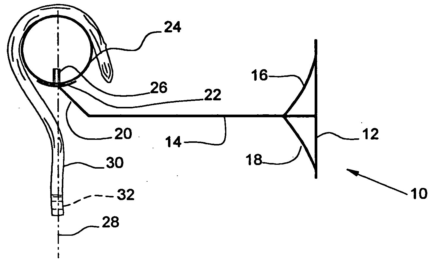
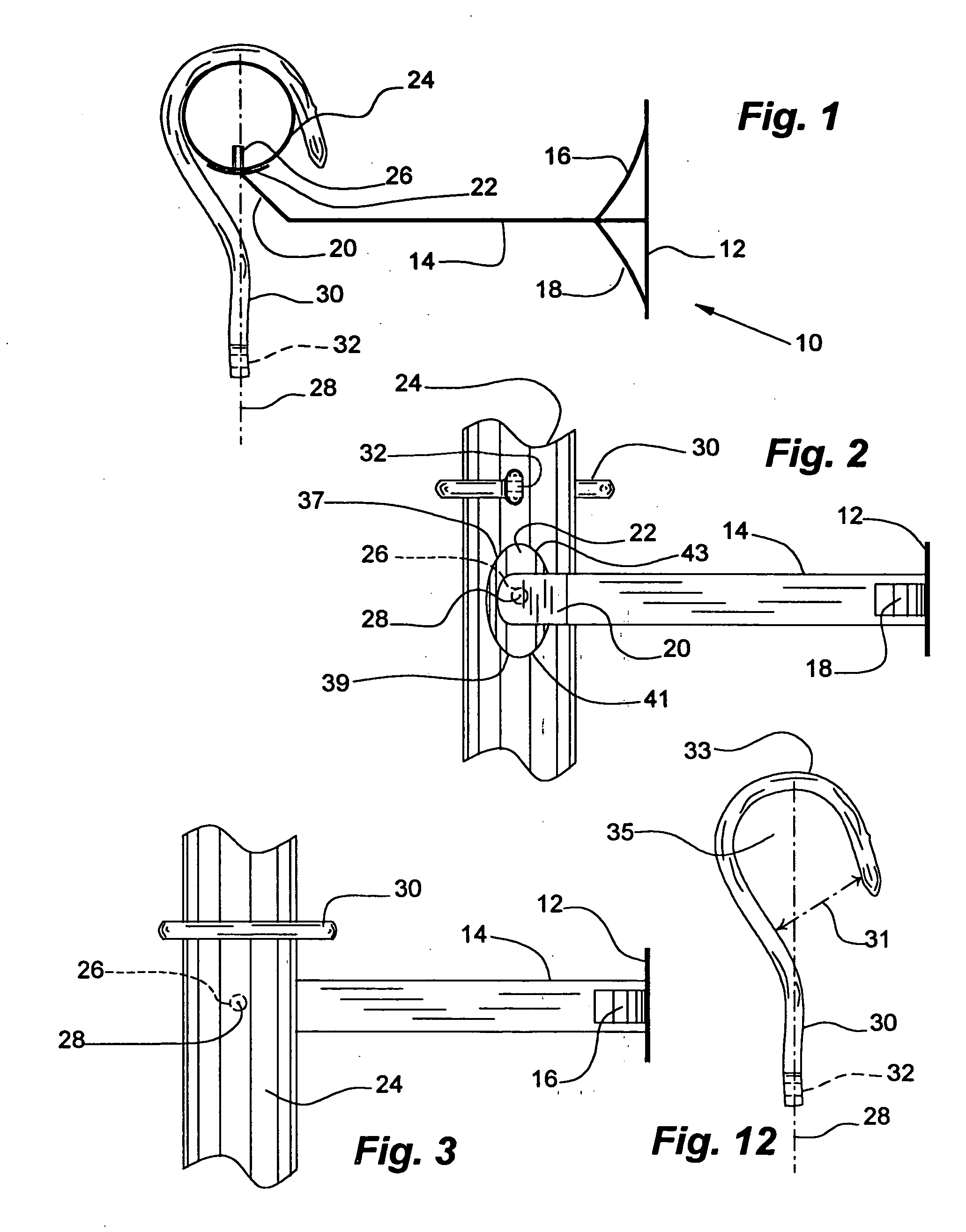
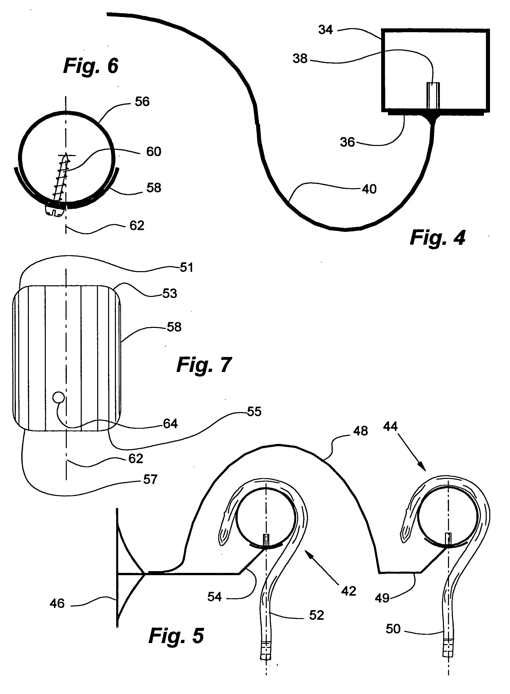
[0026] Referring particularly to the drawings, there is illustrated generally at 10 a drapery mounting system that includes a mounting plate 12, support arm 14, and arm braces 16 and 18 that hold support arm 14 in a substantially rigid configuration with plate 12. In this preferred embodiment support 14 includes an extremity that projects angularly upwardly...


PUM


Abstract

A drapery mounting system comprised of a drapery rod member, a drapery hanger element, and a support member for the rod. The support member is positioned below and intermediate the respective opposed ends of the drapery rod. The support member includes a saddle, a support arm, and a retainer. The saddle is shaped to support a lower external portion of said drapery rod. The saddle extends laterally of the drapery rod for less than about the cross-sectional width of the rod to permit a drapery hanger to pass unimpeded over the saddle. The saddle element preferably has longitudinally opposed edges disposed along the drapery rod. The longitudinally opposed edges are generally convexly arcuate relative to a longitudinal axis of the drapery rod. The support and retention functions are separated. The saddle supports the rod and the retainer releasably retains the drapery rod in engagement with the saddle. A support arm supports from below the saddle. The drapery hanger is slidably supported on the drapery rod member for substantially unimpeded movement past the support member. The drapery hanger typically has a generally question mark shaped form including a hook portion with an open mouth and a depending leg portion, with the open mouth preferably being of sufficient width to pass the drapery rod member laterally therethrough.

Description

RELEATED APPLICATION [0001] Applicant claims the benefit of Provisional No. 60 / 490,673, filed Jul. 28, 2003.BACKGROUND OF THE INVENTION [0002] 1. Field of the Invention [0003] The invention relates in general to methods and devices for pass through sliding drapery mounting systems, and, more particularly, embodiments of the present invention relate to drapery rod mounting systems and associated drapery hangers that permit the hangers to directly engage and slide freely over securely mounted rods. [0004] 2. Description of the Prior Art [0005] Conventional support systems for draperies typically include a horizontally extending rod and hangers or hooks that engage the drapery at a lower end and are supported on the rod at an upper end. Typically, the span of the drapes is such that the rod must be supported at its endpoints and in the middle. This midsection support prevents the midsection of the rod from bending downwardly under the weight of the drapes. Typically, the drapes need to...

Claims


Application Information

Patent Timeline
IPC IPC(8): A47H1/102A47H5/04
CPCA47H5/04A47H1/102
Inventor PUTMAN, MICHAEL
Owner PUTMAN MICHAEL
Learn More