Electric motor and gear drive assembly for driving a vehicle wheel

a technology of electric motors and gear drives, which is applied in the direction of electric propulsion mounting, electric devices, propulsion by batteries/cells, etc., can solve the problems of limited packaging space, serious challenges to effective integration of alternative drive arrangements, and limited potential benefits

Active Publication Date: 2005-02-03
ARVINMERITOR TECH
View PDF18 Cites 19 Cited by
  • Summary
  • Abstract
  • Description
  • Claims
  • Application Information

AI Technical Summary

Benefits of technology

[0008] The combination of the gear drive and electric motor can easily provide speed reduction ratios of twenty to one and can even achieve speed reduction ratios as high as one hundred and seventy-nine to one. Thus, the subject inventio

Problems solved by technology

One shortcoming of such alternative power arrangements is that the potential benefits are limited by the ability to incorporate such systems onto a vehicle.
P

Method used


Image

  • Electric motor and gear drive assembly for driving a vehicle wheel
  • Electric motor and gear drive assembly for driving a vehicle wheel
  • Electric motor and gear drive assembly for driving a vehicle wheel

Examples


Embodiment Construction

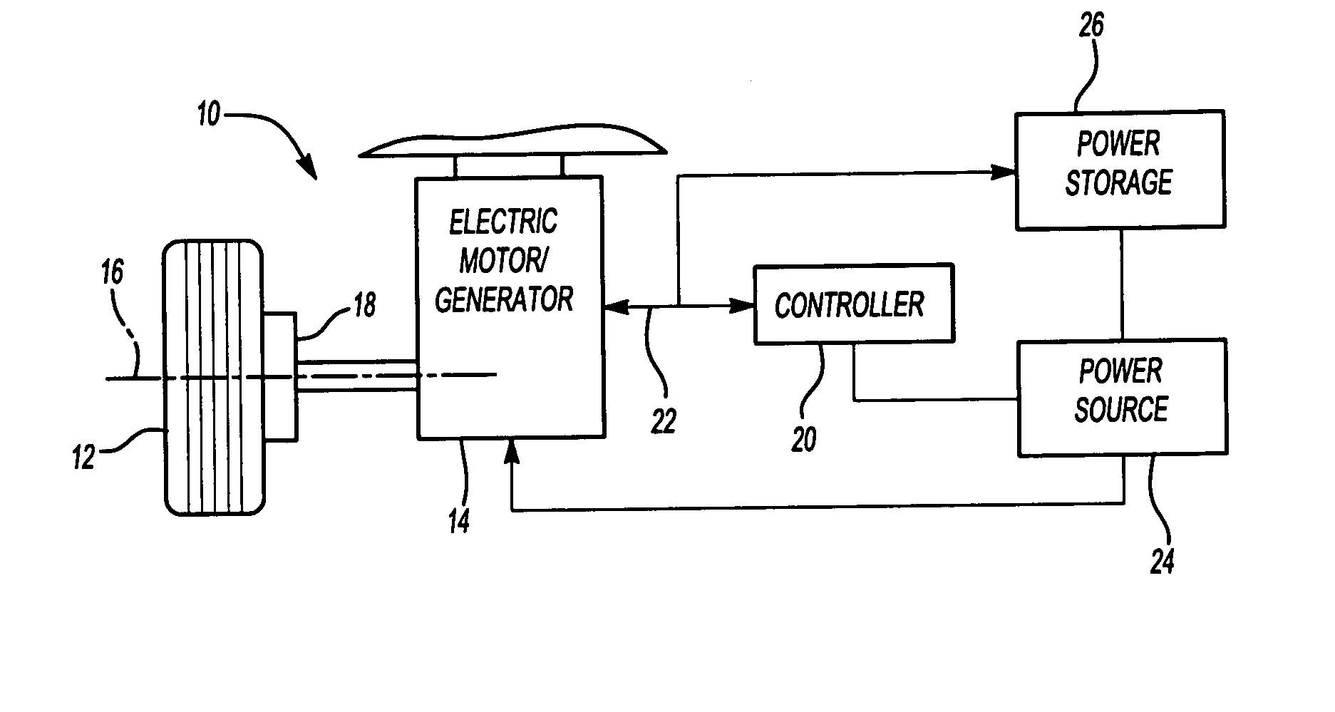
[0017] A drive unit assembly 10 for a vehicle wheel 12 is shown in FIG. 1. The drive unit assembly 10 includes a rigidly mounted electric motor 14 that drives the vehicle wheel 12 about a lateral axis of rotation 16 via a gear drive 18. A controller 20 controls the electric motor 14 with a control signal 22. A power source 24, such as a vehicle battery or other similar source, provides power to the controller 20 and electric motor 14.

[0018] The electric motor 14 is used to directly drive the vehicle wheel 12 and can be used either alone or in conjunction with a conventional internal combustion powertrain. Further, the drive unit assembly 10 could also serve as a retarding mechanism for the vehicle where power generated could be collected and stored in a power storage device 26 for subsequent use by the electric motor 14.

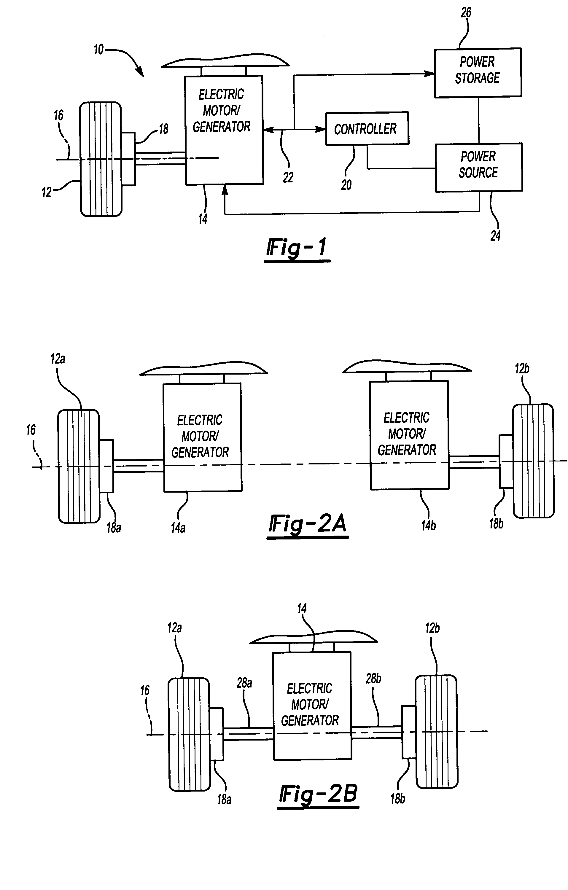
[0019] As shown in FIG. 2A, separate electric motors 14a, 14b can be used to drive the vehicle wheels 12. In this configuration, a first electric motor 14a drives ...


PUM


Abstract

A drive unit assembly for a vehicle wheel includes a rigidly mounted electric motor coupled to the vehicle wheel via a gear drive. The gear drive includes a cycloid or epicycloid gear arrangement that provides significant speed reduction at the wheel.

Description

BACKGROUND OF THE INVENTION [0001] This invention generally relates to a drive unit assembly with an electric motor and gear drive arrangement for driving a vehicle wheel. [0002] Conventional automotive vehicles have been powered by an internal combustion engine that provides driving torque to one or more sets of wheels to propel the vehicle as desired. Recent trends have included incorporating other sources of motive power in place of, or as a supplement to, the internal combustion engine. One such example is an electric hybrid vehicle that utilizes internal combustion engine power and electric power. One shortcoming of such alternative power arrangements is that the potential benefits are limited by the ability to incorporate such systems onto a vehicle. Designs accommodating alternative power sources are typically heavily dependent on current vehicle component configurations. Packaging space is limited and the various component design requirements present serious challenges to ef...

Claims


Application Information

Patent Timeline
IPC IPC(8): B60K7/00B60K17/04
CPCB60K7/0007B60K2007/0038B60K2001/001B60K17/046B60L2220/46Y10S903/906B60L15/2054Y02T10/72B60L50/60Y02T10/64Y02T10/70
Inventor HARRUP, CLIVEBELL, DALE K.KRAMER, DENNIS A.CIRAY, MEHMET S.YAMADA, SILVIO M.HOUSE, DEAN M.PLATNER, DAVID K.ESCHENBURG, DALE J.
Owner ARVINMERITOR TECH
Why Eureka
Try Eureka