Hand-held compact ergonomic laser scanner with integrated scanner activation or data transmission switch in scanner housing

a laser scanner and scanner housing technology, applied in the field of hand-held laser bar code scanners, can solve the problems of increased risk of injury, reduced laser life, drawbacks of automatic scanners, etc., and achieve the effect of economical manufactur

Inactive Publication Date: 2005-02-03
METROLOGIC INSTR
View PDF8 Cites 61 Cited by
  • Summary
  • Abstract
  • Description
  • Claims
  • Application Information

AI Technical Summary

Benefits of technology

[0020] It is, therefore, an object of the present invention to provide an improved bar code scanner of compact size, configured with an integrated scanning head and stand, the entire unit being capable of economical manufacture.

Problems solved by technology

However, there are drawbacks to such a manually activated system including: the requirement that the user must pull the trigger for each scan, whether or not it is the same bar code; the potential for repetitive stress injuries from repetitively pulling the trigger to activate the scanner; and the inability to use a triggered scanner in a hands-free presentation mode without adding extra components or requiring the scanner to be turned on for long periods of time resulting in a decrease in laser life and an increased risk of injury.
However, there are drawbacks to the automatic scanners as well.
It can be difficult to employ automatic scanners in a crowded POS environment where there is a high chance of inadvertently scanning unwanted items.
Bar code menus such as are often found at home improvement and hardware stores present one type of situation where an automatic scanner is at a disadvantage.
Also, moving the automatic scanner across a counter area crowded with objects may produce an unwanted scan when the scanner automatically detects an object.

Method used


Image

  • Hand-held compact ergonomic laser scanner with integrated scanner activation or data transmission switch in scanner housing
  • Hand-held compact ergonomic laser scanner with integrated scanner activation or data transmission switch in scanner housing
  • Hand-held compact ergonomic laser scanner with integrated scanner activation or data transmission switch in scanner housing

Examples


Embodiment Construction

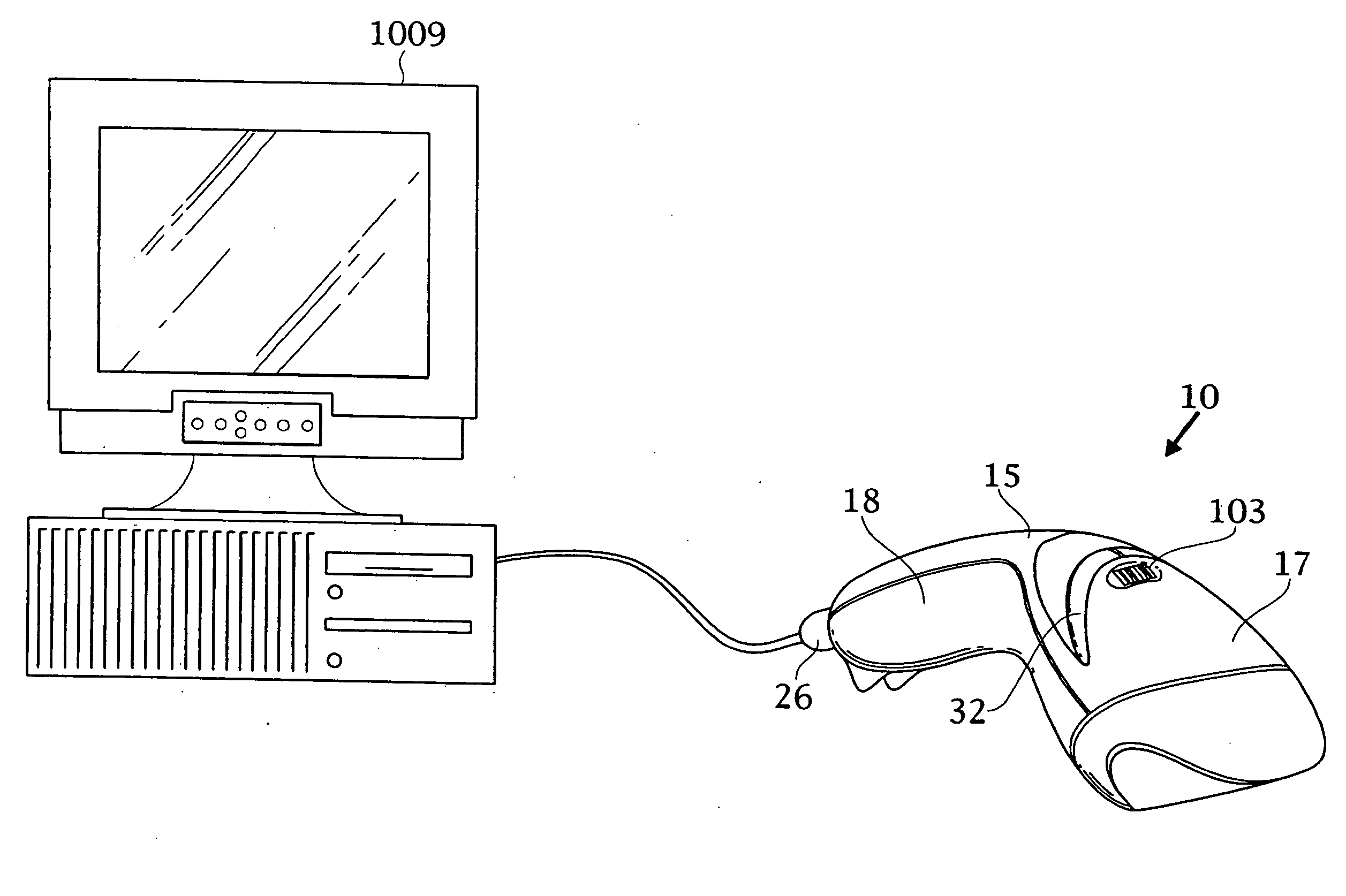
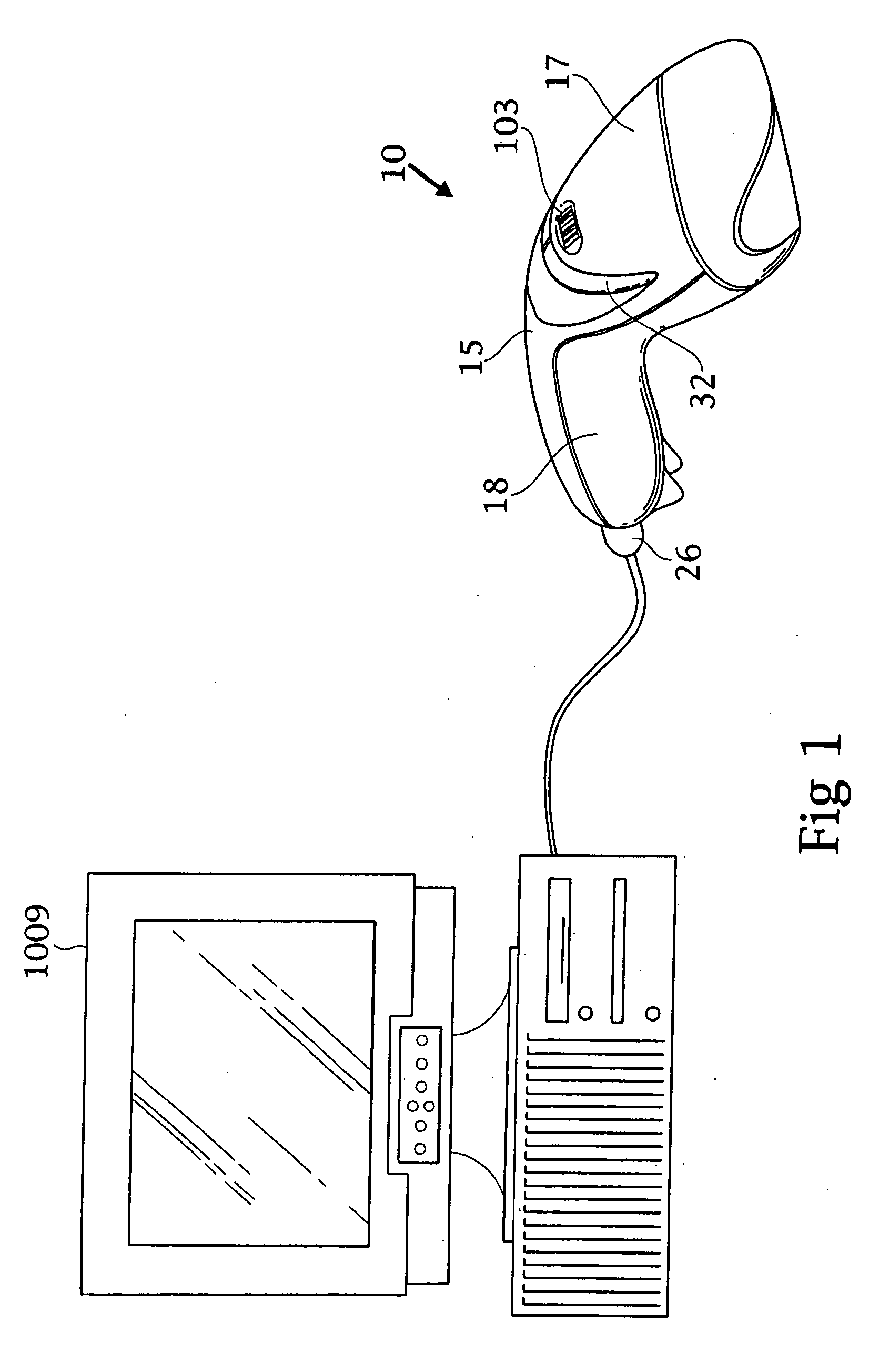
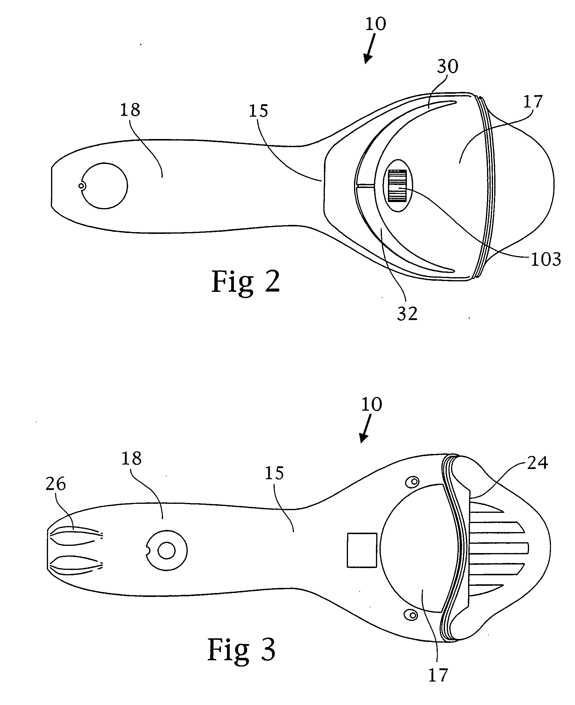
[0053]FIGS. 1-3 are a perspective view, side view and top view of a hand-held compact laser scanner 10 according to one embodiment of the present invention. The compact laser scanner 10 as shown in FIG. 1 incorporates a laser scanning engine 501 mounted inside a hand-supportable / free-standing housing 20. During bar code symbol reading operations, the compact laser scanner 10 automatically generates a visible laser scanning pattern for repeatedly scanning one or more bar code symbols on an object within a bar code symbol reading cycle, and automatically generates a symbol character data string in response to each bar code symbol read thereby. After the bar code symbol reading cycle, manual activation of a data transmission switch 103 integrated into the top section of the hand-supportable housing 20 generates a data transmission control activation signal, thereby enabling a bar code symbol character data string to be selected and transmitted to a host system 1009. A crescent-shaped i...


PUM


Abstract

An ergonomic single-line compact laser bar code scanning system having a compact housing for hand-held disposition at a counter. The scanning system is automatically-activated and includes a bar code symbol reading mechanism contained within a hand-supportable housing having a manually-activatable data transmission switch formed integrally in the housing. During symbol reading operations, the bar code symbol reading mechanism automatically generates a visible laser scanning pattern for repeatedly reading one or more bar code symbols on an object during a bar code symbol reading cycle, and automatically generating a new symbol character data string in response to each bar code symbol read thereby. During system operation, the user visually aligns the visible laser scanning pattern with a particular bar code symbol on an object (e.g., product, bar code menu, etc.) so that the bar code symbol is detected, scanned, and decoded. The user depresses the data transmission switch to produce a data transmission control activation signal and enabling a currently or subsequently produced symbol character data string to be automatically selected and transmitted to a host system.

Description

CROSS-REFERENCE TO RELATED APPLICATIONS [0001] The present application is a continuation-in-part of U.S. application Ser. No. 10 / 104,641 filed Mar. 22, 2002, which is a continuation of U.S. application Ser. No. 09 / 323,292 filed Jun. 1, 1999 (now U.S. Pat. No. 6,257,492), which is a continuation-in-part of application Ser. No. 08 / 645,335 filed May 13, 1996 (now U.S. Pat. No. 5,942,743), and Ser. No. 08 / 645,331 filed 13 May 1996 (now U.S. Pat. No. 5,844,227), and Ser. No. 08 / 943,267, filed Oct. 3, 1997, and Ser. No. 08 / 850,295 filed May 14, 1997, and Ser. No. 08 / 827,118, filed Mar. 27, 1997. [0002] Both of the Ser. No. 08 / 645,335 and Ser. No. 08 / 645,331 applications are continuations-in-part of application Ser. No. 08 / 645,486 filed May 13, 1996 (now U.S. Pat. No. 5,796,091), which is a continuation-in-part of Ser. No. 08 / 615,054 filed Mar. 12, 1996 (now U.S. Pat. No. 6,286,760), which is a continuation-in-part of application Ser. No. 08 / 292,237 filed May 17, 1994 (now U.S. Pat. No. 5,...

Claims


Application Information

Patent Timeline
Patent Type & Authority Applications(United States)
IPC IPC(8): A47F9/04G02B26/10G06K7/10G06K7/14G06K17/00G07G1/00
CPCG06K2207/1018G06K2207/1017G07G1/0045A47F9/046A47F9/047G02B26/10G02B26/106G06K7/10G06K7/10564G06K7/10584G06K7/10594G06K7/10603G06K7/10663G06K7/10673G06K7/10693G06K7/10702G06K7/10792G06K7/10801G06K7/10811G06K7/10851G06K7/10861G06K7/10871G06K7/10881G06K7/10891G06K7/109G06K7/14G06K7/1443G06K17/0022G06K2207/1012G06K2207/1013G06K2207/1016G07F11/002G07F9/002
Inventor BYUN, SUNG HOSCHMIDT, MARK C.RUSSELL, GARRETT K.WILZ, DAVID M. SR.HUDRICK, DONALDNAHILL, JAMES A.
Owner METROLOGIC INSTR
Why Eureka
Try Eureka