Method and apparatus for detecting a liquid spray pattern

a liquid spray pattern and pattern detection technology, applied in the direction of liquid transfer devices, applications, instruments, etc., can solve the problems of affecting the quality and affecting the detection accuracy of liquid spray patterns

Inactive Publication Date: 2005-02-03
NORDSON CORP
View PDF6 Cites 87 Cited by
  • Summary
  • Abstract
  • Description
  • Claims
  • Application Information

AI Technical Summary

Benefits of technology

[0008] The present invention overcomes the foregoing and other shortcomings and drawbacks of liquid dispenser control systems and methods heretofore known. While the invention will be described in connection with certain embodiments, it will be understood that the invention is not limited to these embodiments. On the contrary, the invention includes all alternatives, modifications and equivalents as may be included within the spirit and scope of the present invention.

Problems solved by technology

Otherwise, the circuit board will be left vulnerable to undesirable chemical or moisture attack by any gaps left between the coating tracks or bands.
On the other hand, too much overlap of the adjacent edges may cause undesirable bubbles in the thickened coating areas at the overlap that may also jeopardize quality control.
Unfortunately, while a liquid material dispenser may adequately and reliably dispense uniform conformal coating layers on circuit boards in one production run, changes in the viscosity and / or fluid pressure of the material will often lead to undesirable variations in the liquid spray pattern width.
Additionally, contamination or partial blockage of the nozzle outlet will cause undesirable changes in the spray pattern.
If these changes are not detected prior to a production run, improperly coated boards must be reworked and costly downtime of the conformal coating system is typically required to identify the problem and manually adjust the liquid dispensing system to obtain the desired pattern width and minimal offset.

Method used


Image

  • Method and apparatus for detecting a liquid spray pattern
  • Method and apparatus for detecting a liquid spray pattern
  • Method and apparatus for detecting a liquid spray pattern

Examples


Embodiment Construction

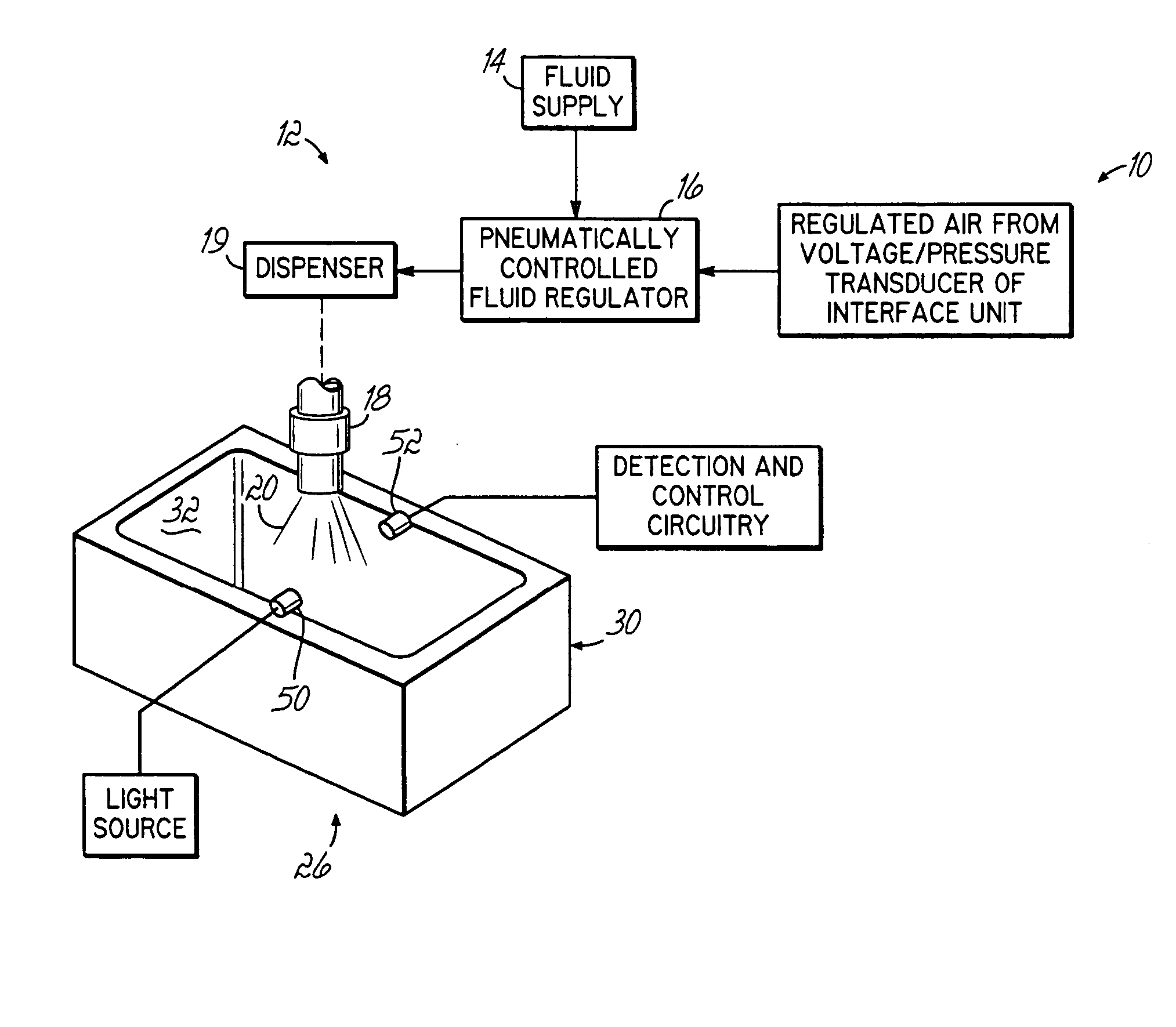
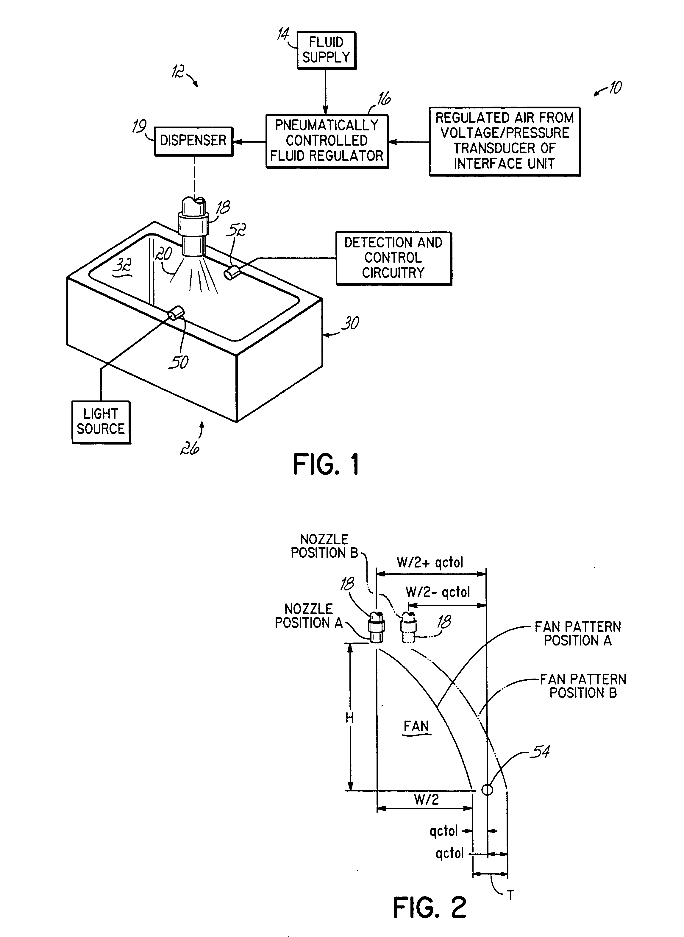
[0023] With reference to the figures, and to FIG. 1 in particular, a liquid spray control system, indicated generally at 10, is illustrated for use in a liquid spray dispensing system, indicated generally at 12. As described in the exemplary embodiment herein, liquid spray dispensing system 12 includes a supply of liquid material 14 that is fluidly connected to a pneumatically controlled regulator 16. The regulator 16 controls the fluid pressure of liquid material within dispensing barrel and nozzle 18 of dispenser 19 so that the liquid material may be dispensed in a flat, fan-like spray pattern. Liquid dispensing system 12 may be a Nordson® Select Coat Dispensing System manufactured and sold by Nordson Corporation of Westlake, Ohio. The barrel and nozzle 18 of the liquid dispensing system may be moved in X-Y-Z directions relative to the substrate under the control of an X-Y-Z robotic movement platform to dispense side-by-side, partially overlapping tracks of liquid material onto a ...


PUM


Abstract

During a liquid spray pattern detection procedure, the sensor (50, 52) is operable to detect the presence or absence of an edge of the dispensed liquid spray pattern. The nozzle (18) of the liquid dispensing system is moved to a predetermined position (A) relative to the sensor (50, 52) to determine the presence or absence of the spray pattern and is then moved to a second predetermined position (B) relative to the sensor (50, 52) to again determine the presence or absence of the spray pattern. Based on these determinations, the width of the spray pattern can be verified. This provides a quick means to verify that the width of the dispensed pattern is within certain tolerances.

Description

CROSS-REFERENCE TO RELATED APPLICATIONS [0001] This application is a continuation of PCT / US03 / 01414, filed Jan. 16, 2003, now pending, which claims the benefit of U.S. Provisional Application No. 60 / 350,827 filed on Jan. 22, 2002, and the disclosures of which are hereby incorporated by reference herein.FIELD OF THE INVENTION [0002] The present invention relates generally to control systems for liquid dispensers and, more particularly, to a control system and method for controlling the dispensed liquid spray pattern of a liquid dispensing system. BACKGROUND OF THE INVENTION [0003] Various liquid dispensing systems have been developed to dispense a liquid spray pattern from a nozzle outlet toward a surface of a substrate. For example, in conformal coating applications, liquid dispensing systems have been designed to dispense flat, fan-like liquid spray patterns of conformal coating material onto a surface of the substrate, such as a printed circuit board. The dispensing nozzle of thes...

Claims


Application Information

Patent Timeline
Patent Type & Authority Applications(United States)
IPC IPC(8): B67D7/08B05B1/04B05B12/00B05B12/08B05B15/00B05B15/02B05C11/00G01B11/02G01B11/24H05K3/00H05K3/12H05K13/00
CPCB05B1/04B05B12/004B05B15/00B05B15/02H05K13/0469H05K3/0091H05K3/1241H05K13/0069G01B11/028B05B12/082B05B15/50B05B12/02
Inventor REIGHARD, MICHAEL A.ESPENSCHIED, KENNETHDONGES, WILLIAM E.MYCKE, JACQUES
Owner NORDSON CORP
Why Eureka
Try Eureka