Method of designing improved spray dispenser assemblies

Inactive Publication Date: 2005-02-03
SC JOHNSON & SON INC
View PDF63 Cites 36 Cited by
  • Summary
  • Abstract
  • Description
  • Claims
  • Application Information

AI Technical Summary

Benefits of technology

[0016] Our invention provides a method of determining design parameters for a design of an improved spray dispenser and designing the same. More preferably, our invention is directed to designing an improved aerosol dispenser assembly that dispenses substantially all of a liquid product (i.e., reduces product retention), in accordance with a predetermined set of performance characteristics. For example, in

Problems solved by technology

The use of CFCs is, however, being phased out due to the potentially harmful effects of CFCs on the environment.
However, we have discovered that a reduction in the propellant content adversely affects the product performance.
Specifically, reducing the propellant content in the aerosol air

Method used


Image

  • Method of designing improved spray dispenser assemblies
  • Method of designing improved spray dispenser assemblies
  • Method of designing improved spray dispenser assemblies

Examples


Embodiment Construction

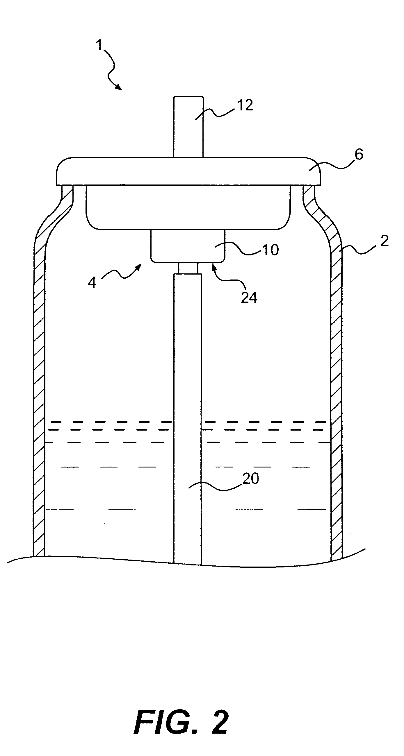
[0032] As shown in FIG. 2, an aerosol dispenser assembly according to our invention generally comprises a container 2 with a valve assembly 4 disposed in the top thereof for selectively dispensing a liquid product from the container 2.

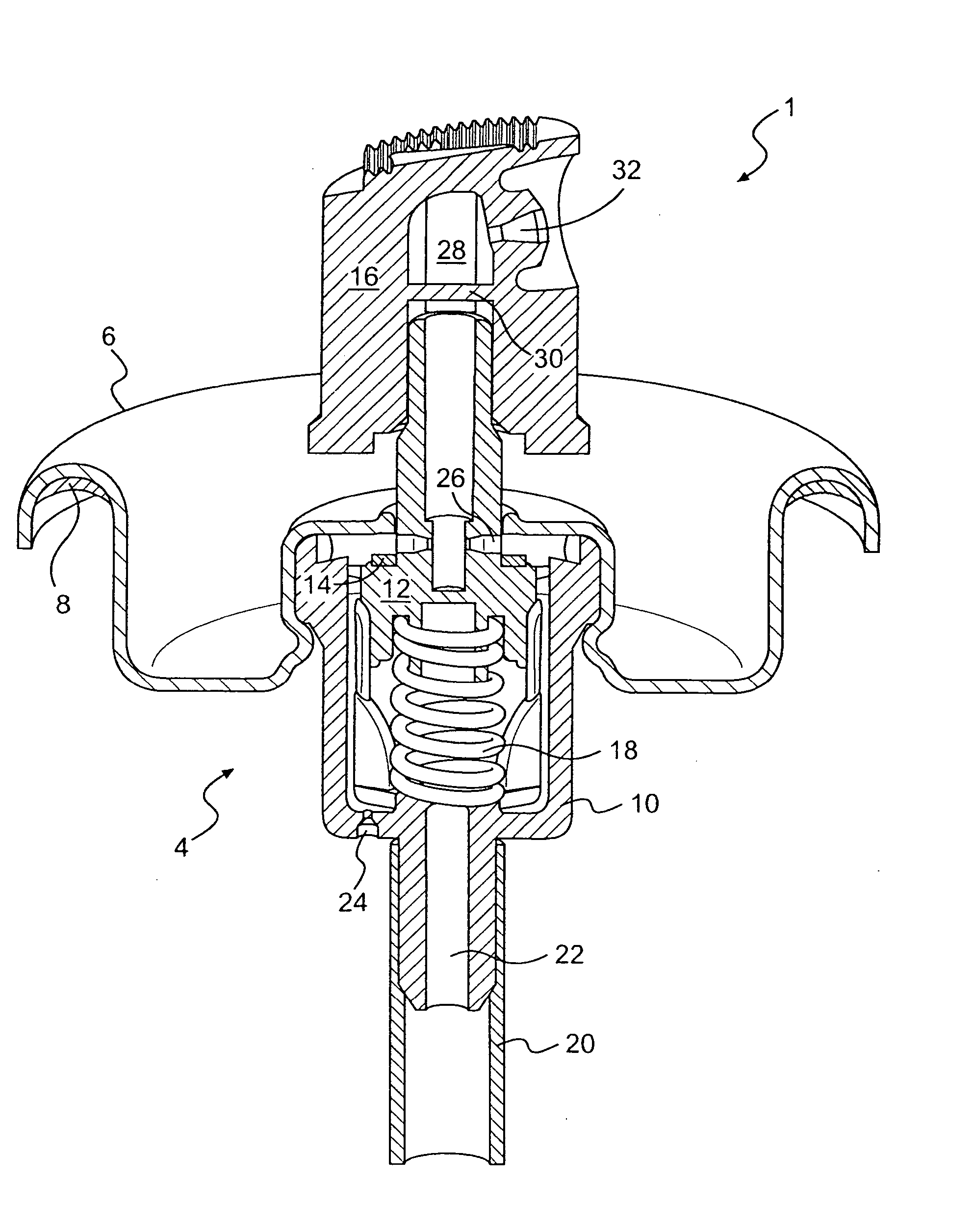
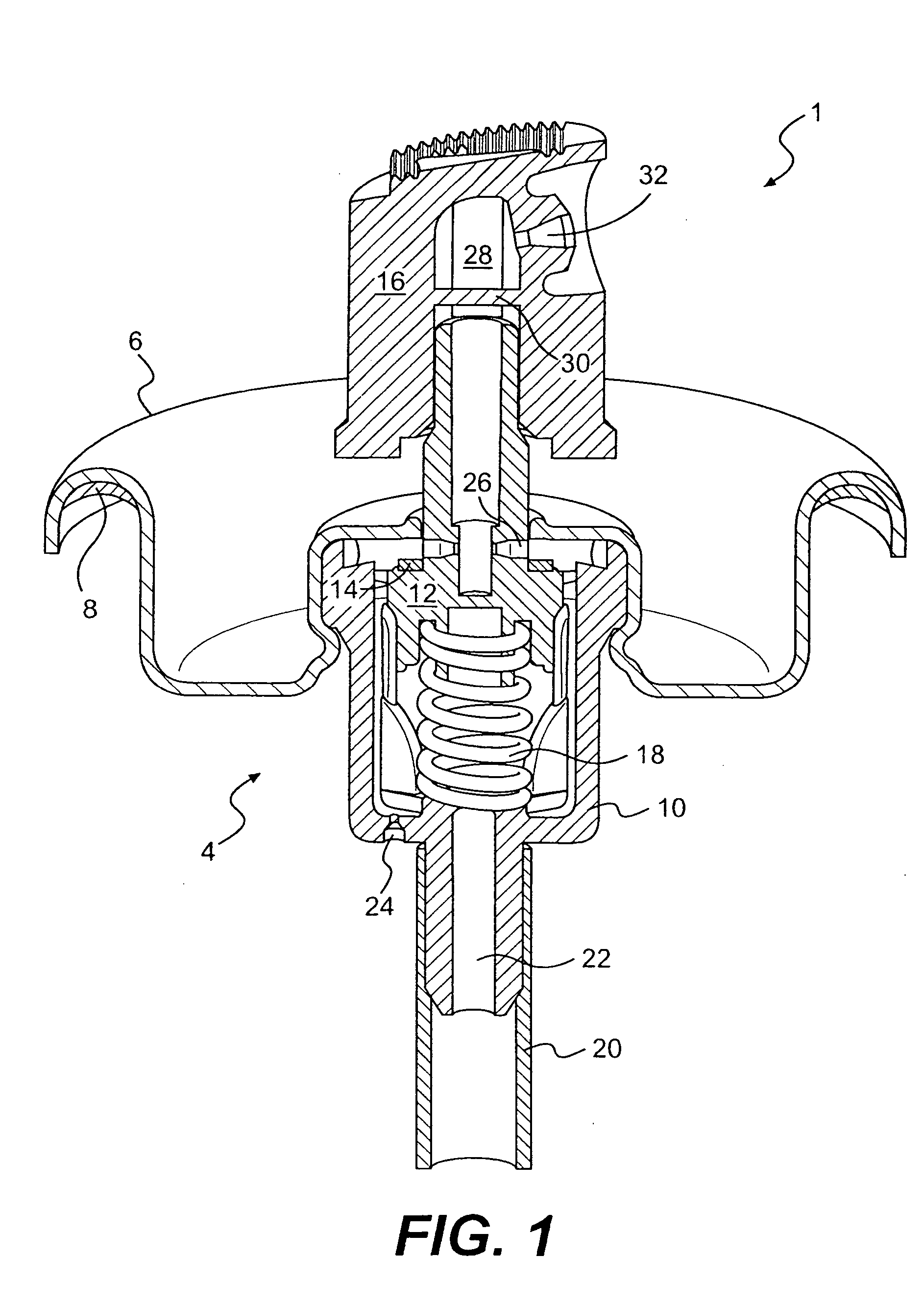
[0033] With reference to FIG. 1, the valve assembly 4 further comprises a mounting cup 6, a mounting gasket 8, a valve body 10, a valve stem 12, a stem gasket 14, an actuator cap 16, and a return spring 18. The actuator cap 16 defines an exit path 28 and an actuator orifice 32. The valve stem 12, stem gasket 14, and return spring 18 are disposed within the valve body 10 and are movable relative to the valve body 10. The valve body 10 is affixed to the underside of the mounting cup 6, such that the valve stem 12 extends through, and projects outwardly from, the mounting cup 6. The actuator cap 16 is fitted onto the outwardly projecting portion of the valve stem 12, and a dip tube 20 is attached to the lower portion of the valve body 10. The whole valve...


PUM


Abstract

A method of determining design parameters for a design of a spray dispenser assembly for dispensing a mist. The method includes identifying one or more preferred performance characteristics of the spray dispenser to be designed and identifying design variables of structures of a spray dispenser assembly that affect those performance characteristics. The method also includes obtaining test data indicative of performance characteristics of spray dispensers at different combinations of values of the design variables. To achieve an improved dispenser design, design parameters are defined for the identified design variables based on the test data. The design parameters provide the preferred performance characteristics when embodied in a spray dispenser.

Description

[0001] This application is a continuation-in-part of copending U.S. patent application Ser. No. 10 / 653,211, filed on Sep. 3, 2003. That application is a continuation-in-part of copending U.S. patent application Ser. No.10 / 350,011, which was filed on Jan. 24, 2003.FIELD OF THE INVENTION [0002] Our invention relates generally to the field of spray dispenser assemblies and methods of designing the same. In particular, our invention relates to the field of designing aerosol dispenser assemblies using a liquefied gas propellant to expel a liquid product from a container. However, while the specific examples discussed herein focus on aerosol spray assemblies, our design method may also be employed to design other spray dispensers, such as those operated by pump action. BACKGROUND OF THE INVENTION [0003] Aerosol dispensers have been commonly used to dispense personal, household, industrial, and medical products, and provide a low cost, easy to use method of dispensing such products. Typica...

Claims


Application Information

Patent Timeline
IPC IPC(8): B65D83/14
CPCB65D83/752B65D83/48
Inventor VALPEY, RICHARD S. IIIGOELZ, JOHN F.ROHRER, MICHAEL J.
Owner SC JOHNSON & SON INC
Why Eureka
Try Eureka