
Low maintenance spa control system

a control system and low maintenance technology, applied in the field of electronic control systems, can solve the problems of inability to physically separate functions, inconvenient use for users, and the cost of maintaining these control systems has grown to unacceptable levels, so as to improve reliability and maintainability, the effect of easy removal

Active Publication Date: 2009-05-21
BALBOA WATER GRP LLC
View PDF18 Cites 40 Cited by
  • Summary
  • Abstract
  • Description
  • Claims
  • Application Information

AI Technical Summary

Benefits of technology

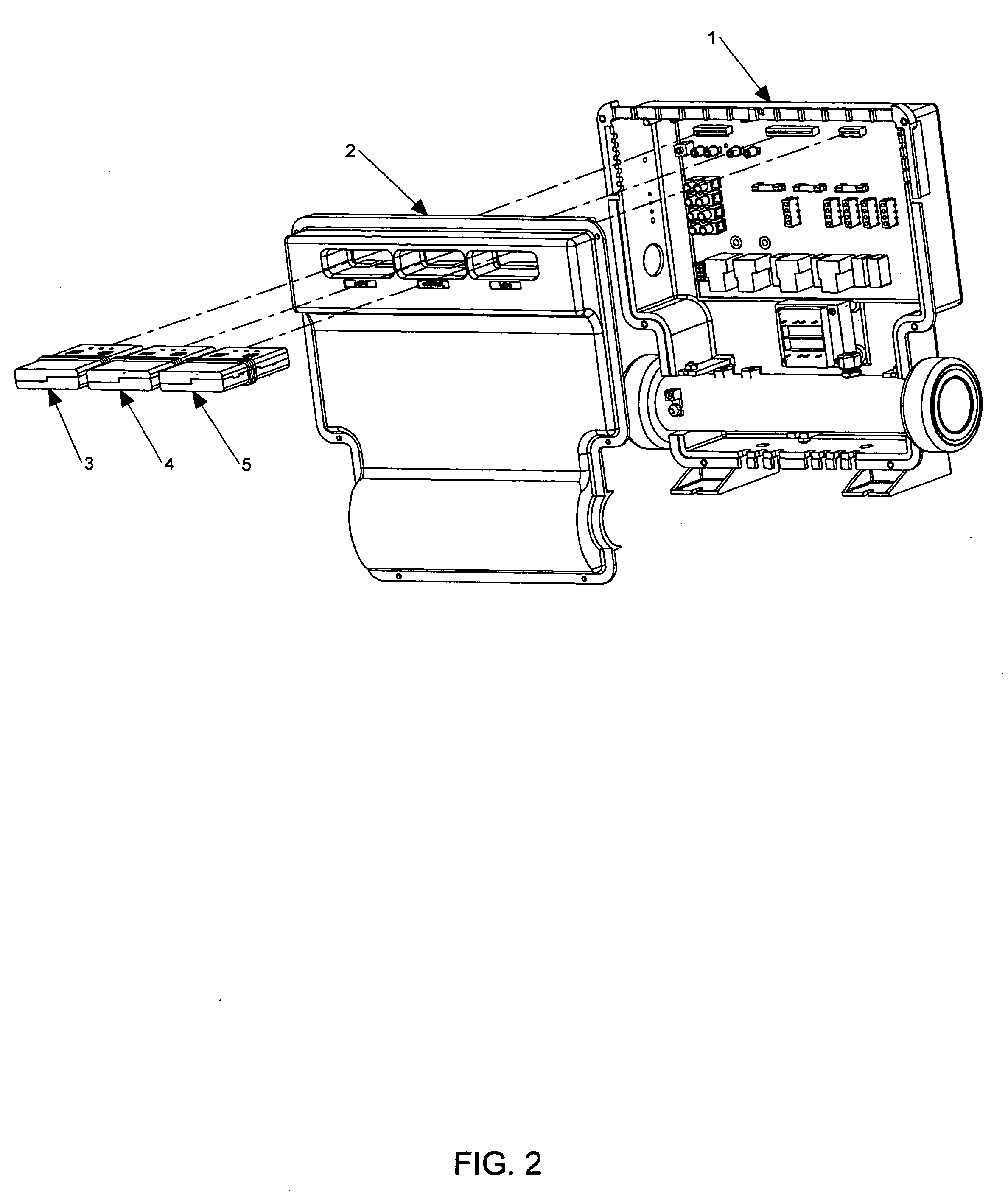
[0010]The present invention teaches a highly integrated spa control system that improves reliability and maintainability through extensive use of modular functions and segregation of high voltage and low voltage circuit boards. A major benefit in manufacturing is also enjoyed by using all SMT construction on low voltage boards and all thru-hole construction on high voltage boards. In a preferred embodiment, the modular functions are constructed with low voltage, SMT circuits and enclosed in plastic housings. The modules are designed to be easily removable from the main board with the cover of the pack still in place.
[0013]A preferred embodiment places a sensor as near as possible to the actual heating element. This placement provides the fastest response to flow or water problems, yet does not risk damage to the sensor or the heater because of the almost instant reaction of the sensor.
[0016]Improved designs for other control functions are also disclosed. The audio circuit of a preferred embodiment uses Class D amplifiers contained in a single integrated circuit, requiring less space and generating less heat. The FM tuner is also a reliable, single chip design requiring less maintenance. A digital signal processor (DSP) on a single chip eliminates extensive crossover networks.
[0017]A single LED control circuit furnishes power to various LED lighting locations in the spa. This arrangement allows integrated control from a user interface, with special features like dimming and music modulation of the LEDs easily achievable.
[0018]A key to low maintenance, other than improved reliability, is the ease in which defective parts can be identified and replaced. Major control functions in a preferred embodiment are separated into removable modules. A built-in diagnostic routine isolates defective components, similar to the Hollaway patent, but performs the required diagnostic steps each time a component is activated. This real-time evaluation is desired so that an associated multi-colored LED on the spaside panel, or any other user interface, can immediately show a color associated with the performance status of the activated component.

Problems solved by technology

Optional equipments, such as stereo sound systems, are most often separate from the main control system, creating some inconvenience for the user.
Control systems having some integration still make little attempt to physically separate functions for the purpose of troubleshooting and replacement of components.
Likewise, it is common to find circuit boards with mixed technology (SMT and thru-hole), due to the need to have high power and low power parts on the same board, which requires extra processing steps for each of these boards.
As electronic spa control systems have become more common, the cost of maintaining these control systems has grown to unacceptable levels.
This high cost is attributable to the complexity of design, with higher part counts and attendant failure rates, as well as the need for technicians with greater training.
If the positive difference is greater than a prescribed amount, it is assumed that there is a flow problem causing the heat buildup.
No consideration is made for one of the sensors being defective or for incorrect placement on the heater.
While this is a useful improvement for providing a backup for the regular high limit control, no provision is made to use the temperature sensors to back up the flow monitoring system.

Method used


Image

  • Low maintenance spa control system
  • Low maintenance spa control system
  • Low maintenance spa control system

Examples


Embodiment Construction

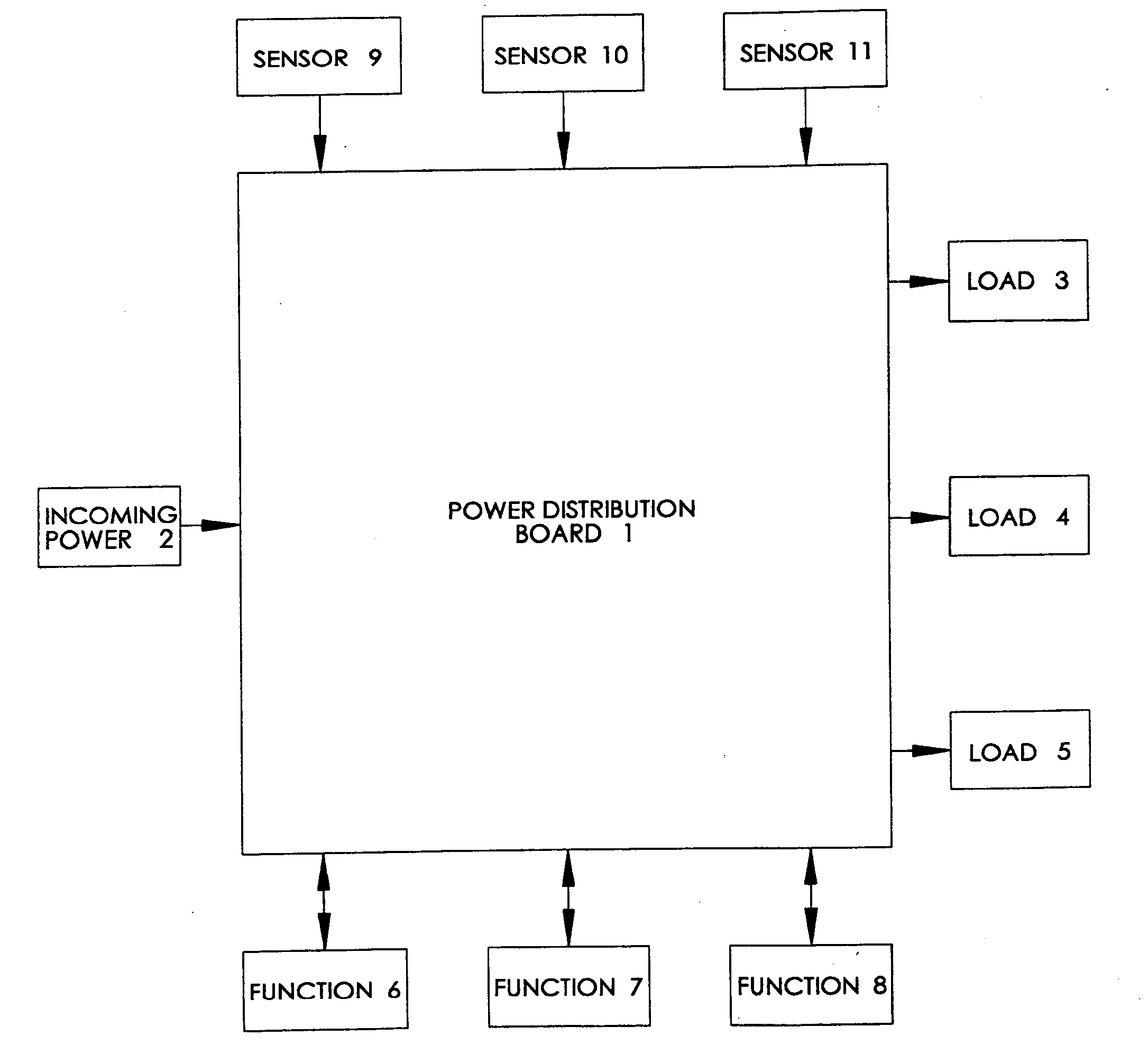
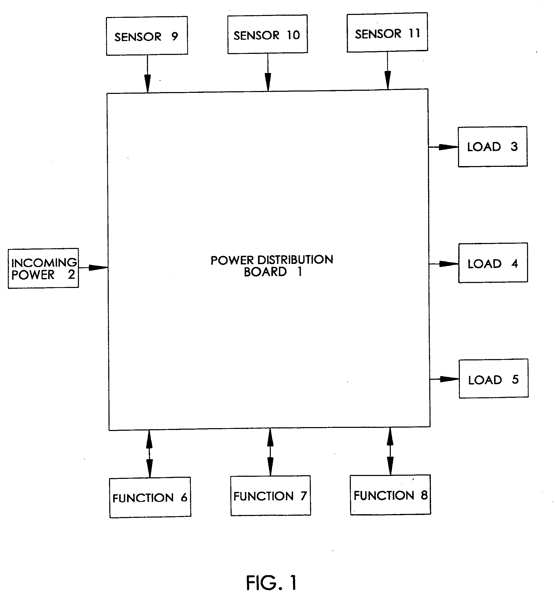
[0026]Referring to FIG. 1, a spa control system according to the present invention may consist of a Power Distribution Board 1 to receive Incoming Power 2 and to distribute the power to Load 3, Load 4, and Load 5, where 5 represents any number of additional loads. Typical electrical loads in a spa may consist of single speed motors, multiple speed motors, variable speed motors, water heaters, LEDs, light bulbs, speakers, video displays, cover alarm sound devices, cover lift devices, wave producing devices, ozone producing devices, chemical dispensers for chlorine or bromine, devices for producing chlorine or bromine, and valve controllers.

[0027]Function 6, Function 7, and Function 8, where 8 represents any number of additional functions, include at least a logic function to manage the various spa operations such as water temperature control, motor activation, and communication with user interfaces. Other functions may include a light function made up with LED and bulb driver circuit...


PUM


Abstract

A spa control system designed to reduce maintenance cost by providing modular construction for major control functions, with built-in diagnostic capabilities for isolating defective spa components. Multi-colored LEDs on the spaside panel constantly report the status of each component of the spa as well as the status of the functional modules themselves. Each time a component is activated, measurements of operational parameters, such as load currents, are instantly made and evaluated so that the proper LED color can be presented at the spaside. Since major functions such as audio, LED control, wireless, and spa logic are separated into removable modules, repair of the control system requires less time and less skilled personnel. Other design improvements, such as direct monitoring of heater element temperature and the purging of pumps on an as required-basis, enhance the spa's overall reliability and thus reduce the need for maintenance.

Description

BACKGROUND OF THE INVENTION[0001]1. Field of the Invention[0002]The present invention relates to electronic control systems used in spas and hot tubs.[0003]2. Description of Related Art[0004]Electronic controls have been developed for spas that give the user effective control of the various electrical equipment, such as motors, lights, and heaters. Typically, a spaside control with a microprocessor is used to manage the overall spa function. The spaside communicates with other components in the control system which turn the equipment on and off according to programming instructions in the spaside and inputs from various sensors. Optional equipments, such as stereo sound systems, are most often separate from the main control system, creating some inconvenience for the user.[0005]Control systems having some integration still make little attempt to physically separate functions for the purpose of troubleshooting and replacement of components. Likewise, it is common to find circuit boar...

Claims


Application Information

Patent Timeline
IPC IPC(8): G05B9/02G06F1/28G05D23/19G05B15/02G06F1/32
CPCA61H33/005A61H2033/0066A61H2201/0176A61H2201/5043G05D23/1931A61H2201/5087F24H1/0081F24H9/2028A61H2201/5082F24H1/54
Inventor HOLLAWAY, JERRELL P.
Owner BALBOA WATER GRP LLC
Learn More