Phase Shifter Design Improvements

a phase shifter and design improvement technology, applied in waveguides, delay lines, coupling device connections, etc., can solve the problems of large number of solder joints, easy damage to solder joints between coaxial cables and pcbs, complicated linkages of known electrically-driven phase shifters, etc., to achieve effective zero compression, adequate clamping force, and complicating installation

Inactive Publication Date: 2011-03-17
COMMSCOPE TECH LLC
View PDF3 Cites 31 Cited by
  • Summary
  • Abstract
  • Description
  • Claims
  • Application Information

AI Technical Summary

Benefits of technology

[0016]Coaxial cable used in cellular communication networks is designed such that the cable diameter falls within common manufacturing tolerances. Due to the variance in diameter in all coaxial cable, known single piece cable clamps are often unable to adequately secure cable of a diameter on the narrow and possibly on the wide extreme of the cable diameter variance. Known rigid cable clamps make use of some degree of compression in the non-metallic outer jacket of known coaxial cables. However, the coaxial cables contemplated by the current invention are often generally rigid. The cables have very rigid plastic outer jackets which have effectively zero compression. To solve the problem of providing a clamp force onto varying diameter of rigid cable, the current invention incorporates a flexible portion which accommodates coaxial cable diameter variation, but still offers adequate clamping force. The cable clamp of the current invention is composed of plastic-based material having properties that allow for a flexible portion as well as a rigid clamping portion. One advantage of the current invention is that the clamp consists of a single part to be used for securing coaxial cable. This is an improvement over known clamps that employ multiple parts, such as mounting bolts or screws, which tend to complicate installation and increase cost. Another advantage of the current invention is that the clamp engages a rigid mating part such as the cable housing, thus securing the cable between the clamp and the housing. A further advantage of the current invention is that the clamp will be removable by releasing the mounting clips manually.

Problems solved by technology

However, the known electrically-driven phase shifters tend to suffer from complicated linkages, can typically be driven only from one end, and would require substantial engineering to adapt from one antenna design to another.
Additionally, the presence of the phase shifter assemblies in coaxial cable fed assemblies also typically means that a large number of solder joints are present.
The solder joints between coaxial cables and PCBs are susceptible to damage unless the joint is protected by a strain relief.
However, such strain relief was applied after the solder joint was made, thereby allowing a period of time when the solder joint was susceptible to damage.
The solder joints within the base station antennas are susceptible to damage from multiple sources.
The normal movements of the cables when being dressed into their final positions during assembly can place stress on solder joints.
The solder joints may be damaged during installation of the base station antenna.
Solder joints may also experience damage in the field from vibration during normal operation, or as a result of weather or other external forces.
Damage to the solder joint can lead to undesirable passive intermodulation (PIM) effects in the antenna transmission characteristics.
The mechanical failure of solder joints in a phase shifter assembly adds to the cost of producing an antenna panel.
This is especially true when the solder joint failure is not detected until after the antenna panel has been assembled.
Solder joints have been known to have been mechanically compromised by simply moving a known phase shifter assembly from an assembly station to a test station.
This previous method suffers from several deficiencies.
A rigid clamp manufactured to a specific size is often too large to secure a coaxial cable, because rigid clamps must be designed to accommodate the largest cable diameter within a given tolerance.
Second, a rigid clamp does not address the problems associated with damage to solder joints due to vibration.
In addition to suffering from the same deficiencies as the basic rigid clamp, the rigid clamp affixed by screws has the disadvantage of extra parts and increased cost.

Method used


Image

  • Phase Shifter Design Improvements
  • Phase Shifter Design Improvements
  • Phase Shifter Design Improvements

Examples


Embodiment Construction

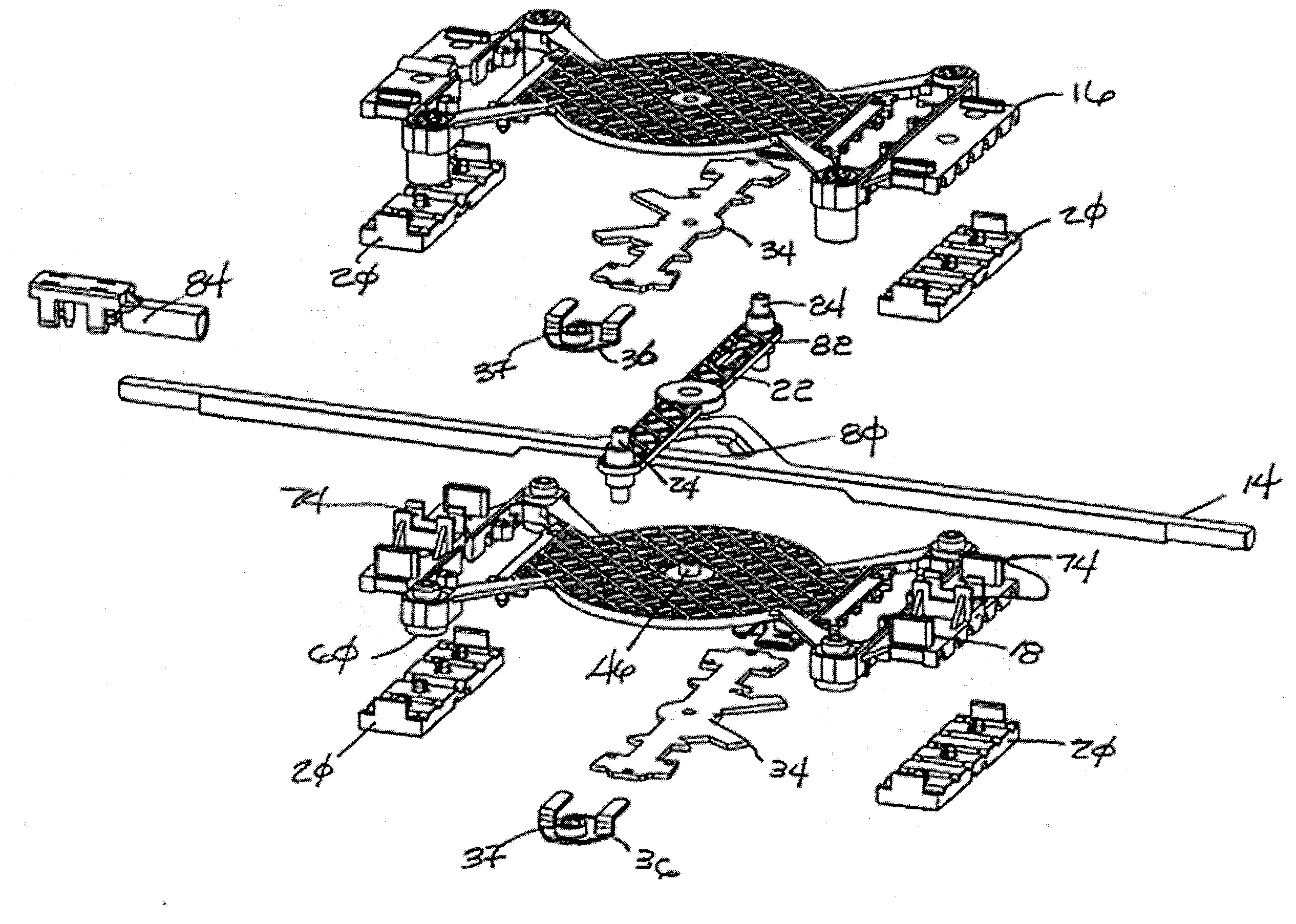
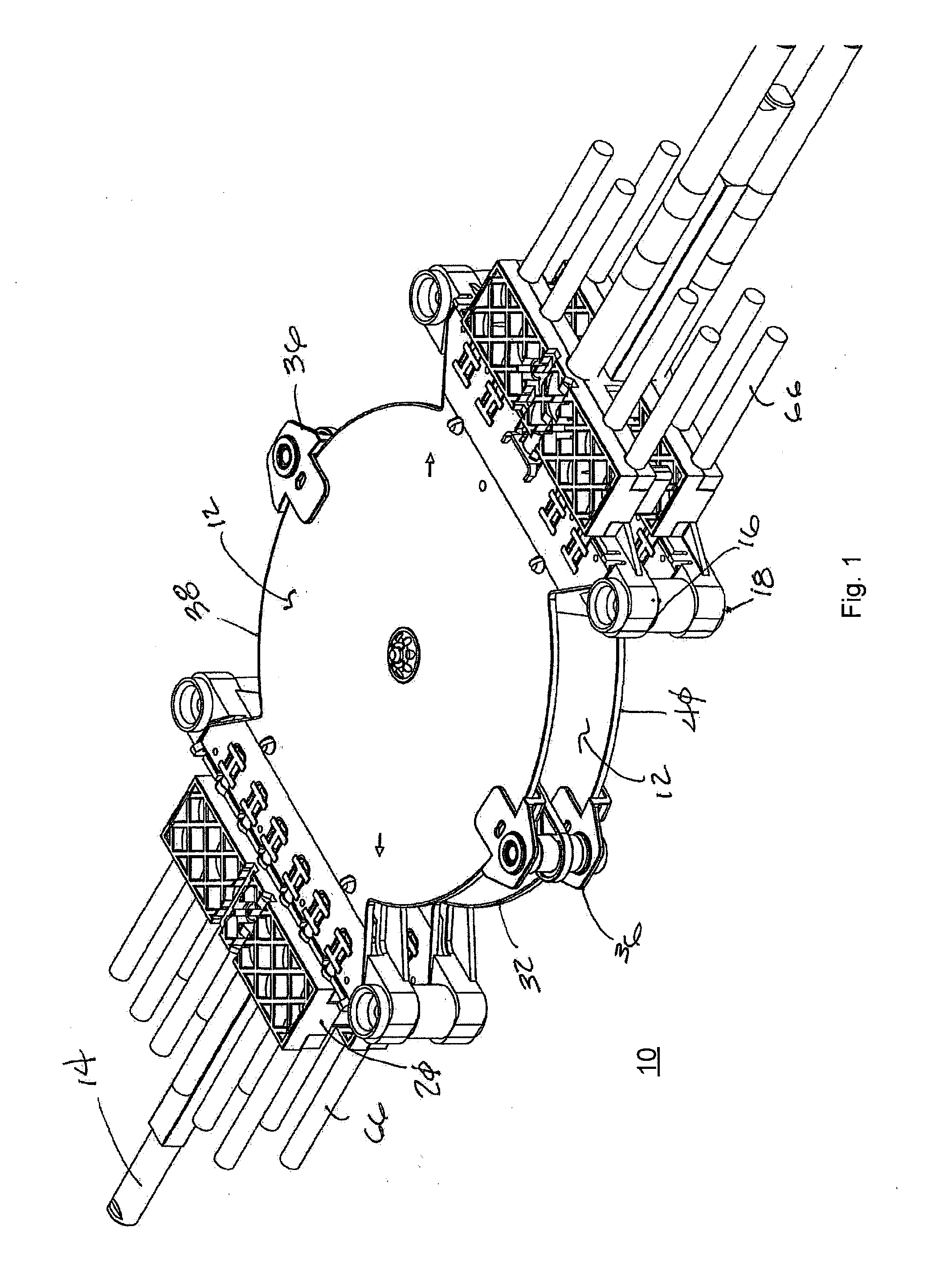
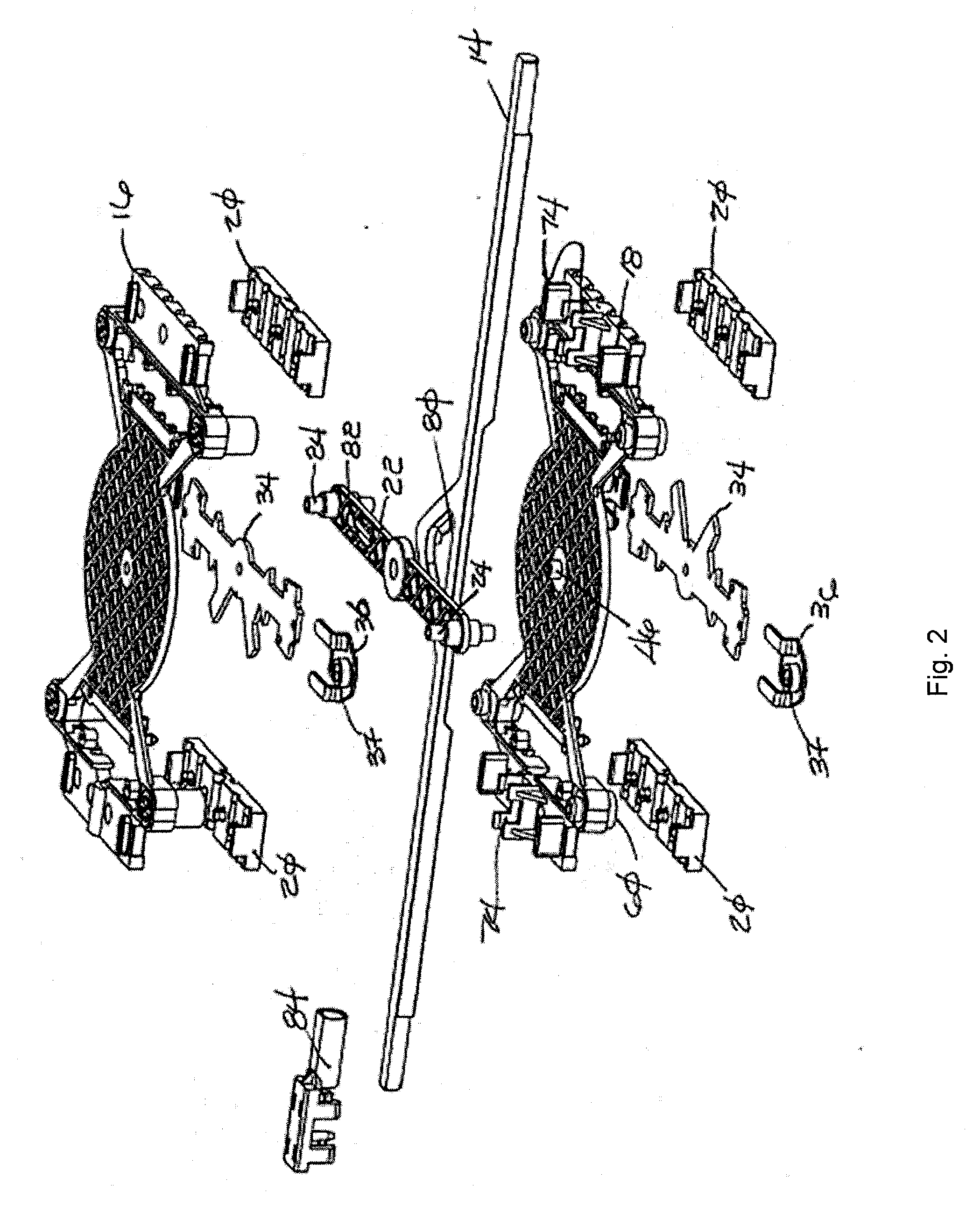
[0035]Referring to FIGS. 1-3, an improved phase shifter assembly 10, according to one example of the present invention, includes one or more phase shifter sub-assemblies along with supporting structure and actuating components. In an illustrated example, a phase shifter assembly 10 includes a plurality of phase shifters 12 actuated by a common throw arm 14. In that example, support structures and actuating components of the phase shifter assembly 10 includes a top phase shifter carrier 16, a bottom phase shifter carrier 18, cable strain relief clamps 20, a pivot arm 22, and the throw arm 14.

[0036]Referring to FIGS. 3, 5 and 7, the phase shifters 12, in one illustrated example, are implemented on a first printed circuit board (PCB) 30, a second printed circuit board 32, wiper printed circuit boards 34 and wiper supports 36. Other phase shifter structures may be implemented without departing from the present invention. The above components may be arranged so that the first PCB 30, a w...


PUM


Abstract

An improved phase shifter assembly is provided. The phase shifter assembly may comprise first and second sub-assemblies with certain common actuating elements. In one example, a first phase shifter sub-assembly is provided, the first phase shifter sub-assembly including a first phase shifter carrier, a first phase shifter printed circuit board mounted on the first phase shifter carrier, a first wiper printed circuit board coupled to an input of the first phase shifter printed circuit board and having at least a first end coupled to transmission lines on the first phase shifter printed circuit board, and at least one wiper support mechanically coupling the first wiper printed circuit board to the first phase shifter printed circuit board. A second phase shifter is similarly provided. Common actuating elements may include a pivot arm and a throw arm. The pivot arm may be rotatably mounted in the phase shifter assembly and be configured to engage a wiper support of at least one of the first and second phase shifter sub-assemblies. The throw arm may be mounted such that when the throw arm is moved linearly, the pivot arm rotates around a pivot.

Description

CROSS-REFERENCE TO RELATED APPLICATIONS[0001]The present invention claims priority to U.S. Provisional Patent Application No. 61 / 242,240 filed Sep. 14, 2009 titled: “Phase Shifter Design Improvements.”FIELD OF THE INVENTION[0002]The field of the invention relates generally to improvements in phase shifter assemblies, including improvements to manufacturing, durability, and cost reduction.BACKGROUND OF THE INVENTION[0003]Wireless mobile communication networks continue to evolve given the increased traffic demands on the networks, the expanded coverage areas for service and the new systems being deployed. Cellular (“wireless”) communications networks rely on a network of base station antennas for connecting cellular devices, such as cellular telephones, to the wireless network. Many base station antennas include a plurality of radiating elements in a linear array. Various attributes of the antenna array, such as beam elevation angle, beam azimuth angle, and half power beam width may b...

Claims


Application Information

Patent Timeline
Patent Type & Authority Applications(United States)
IPC IPC(8): H01P1/18
CPCH01R13/5812H01P1/184
Inventor BRADLEY, EDDIE R.DICKERSON, CALVINRODGER, DEREK
Owner COMMSCOPE TECH LLC
Why Eureka
Try Eureka