Arm apparatus for mounting electronic devices

a technology for mounting electronic devices and arm apparatuses, which is applied in the direction of building scaffolds, machine supports, furniture parts, etc., can solve the problems of difficult assembly, bulky and cumbersome, and inconvenient manufacture of extension arms b>10/b> of the prior art, and achieves the effect of easy manufacture and assembly and inexpensiveness

Inactive Publication Date: 2005-02-03
ODDSEN ODD N JR
View PDF81 Cites 17 Cited by
  • Summary
  • Abstract
  • Description
  • Claims
  • Application Information

AI Technical Summary

Benefits of technology

[0014] The present invention, in accordance with one embodiment, relates to an extension arm suitable for mounting a flat-screened electronic peripheral device, such as a computer monitor or television. The extension arm is inexpensive and easy to manufacture and assemble, and permits a flat-screen device to be mounted substantially flush with a mounting surface.

Problems solved by technology

Extension arms 10 of the prior art, such as the one shown in FIGS. 1-7 and others like it, are ill-suited for flat-screen monitors and televisions, in that they are bulky and cumbersome.
Additionally, the extension arms 10 of the prior art are costly to manufacture and difficult to assemble.

Method used


Image

  • Arm apparatus for mounting electronic devices
  • Arm apparatus for mounting electronic devices
  • Arm apparatus for mounting electronic devices

Examples


Embodiment Construction

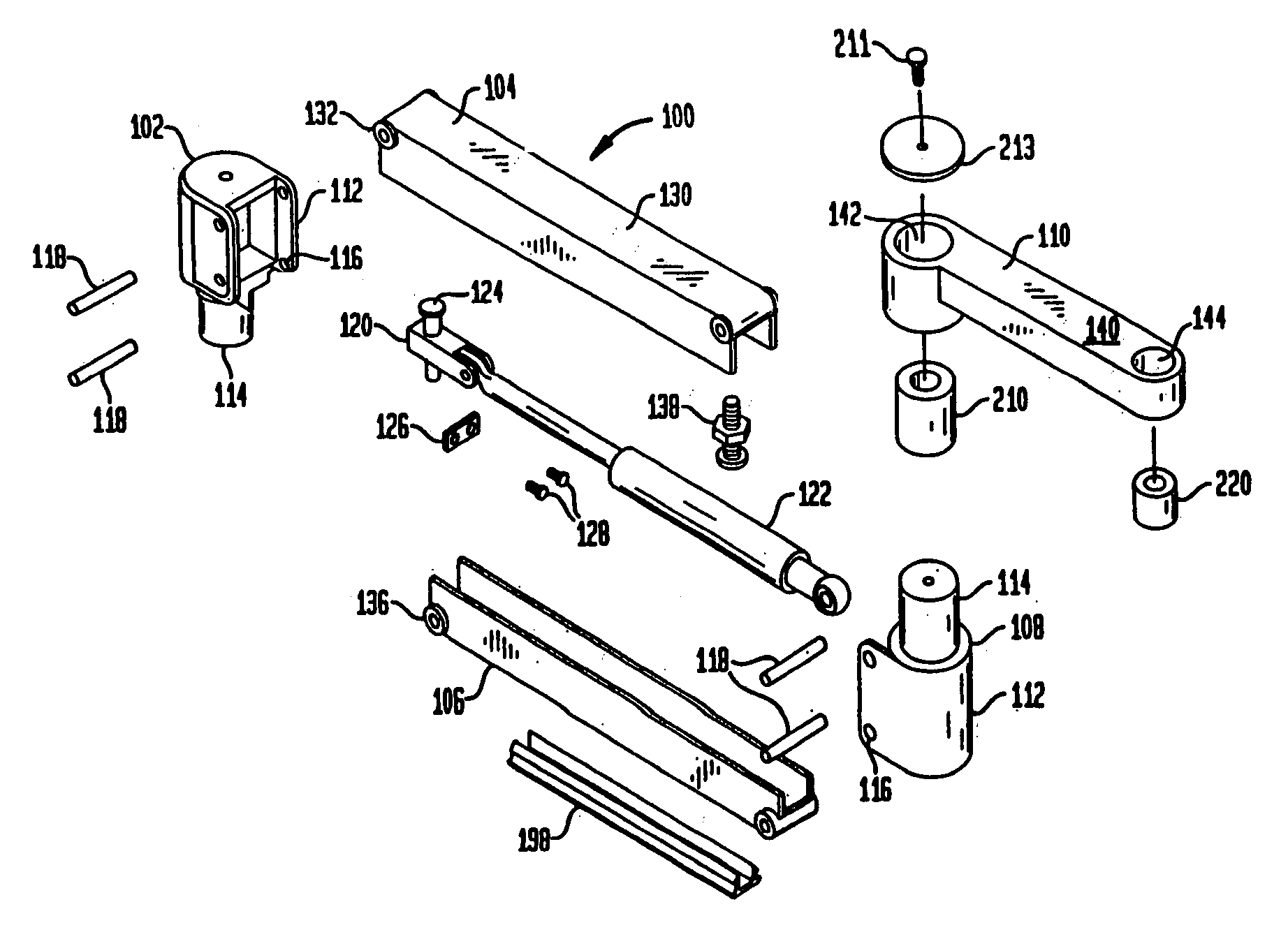
[0035] The present invention, in accordance with one embodiment, relates to an extension arm suitable for mounting a flat-screen electronic peripheral device, such as a computer monitor or television, and the method of manufacturing the extension arm. FIG. 8 is an exploded assembly drawing of the extension arm, for adjustably mounting a device to a support mount, according to one embodiment of the invention.

[0036] In the embodiment shown, the extension arm 100 comprises a first end cap 102, an upper channel 104, a lower channel 106, a second end cap 108, and a forearm extension 110. The first end cap 102 and the second end cap 108 both include a partially enclosed housing 112 and a shaft 114. The partially enclosed housing 112 of both the first and the second end caps 102, 108 is configured with, for example, holes 116 to receive a connection mechanism, such as a pin 118, therethrough. The shaft 114 of the first end cap 102 is configured to be inserted for pivotable rotation in a s...


PUM

PropertyMeasurementUnit
degree anglesaaaaaaaaaa
angleaaaaaaaaaa
incline angleaaaaaaaaaa

Abstract

An extension arm suitable for mounting a flat-screen electronic peripheral device, including a forearm extension having at one end a first coupling for attachment to a tilter, a platform or other means for supporting a flat-screen device and at the other end a second coupling. The extension arm also includes a pair of end caps, each having a shaft. The shaft of the first end cap is pivotably rotatable in a support mount, such as a wall, desk or pole mount. The shaft of the second end cap is pivotably rotatable in the second coupling of the forearm extension. The extension arm also includes an upper channel and a lower channel. Each channel has at opposite ends a pair of integrally cast rollers which are pivotably attached to each of the end caps. The upper and lower channels and the end caps form an adjustable parallelogram.

Description

REFERENCE TO CROSS-RELATED APPLICATIONS [0001] The present application is a continuation application which claims the benefit of the filing date of United States Divisional patent application Ser. No. 10 / 305,568, filed Nov. 27, 2002, which is a divisional of U.S. patent application Ser. No. 10 / 166,419, filed Jun. 10, 2002, which is a continuation of application Ser. No. 09 / 405,628, filed Sep. 24, 1999, now U.S. Pat. No. 6,478,274, which claims the benefit of the filing date of U.S. Patent Application No. 60 / 133,378, filed on May 10, 1999, all of which are entitled “Arm Apparatus for Mounting Electronic Devices”, the disclosures of which are incorporated herein by reference.BACKGROUND OF THE INVENTION [0002] This invention relates to an arm apparatus for mounting electronic devices and a method for manufacturing the arm apparatus, and more specifically to an extension arm suitable to mount a flat-screened electronic peripheral device, such as a computer monitor or television and the ...

Claims


Application Information

Patent Timeline
Patent Type & Authority Applications(United States)
IPC IPC(8): F16M11/04
CPCA47B2200/0088F16M11/04F16M11/2014F16M11/2092F16M11/24Y10T29/49988F16M2200/063Y10T29/49826Y10T403/57Y10T403/5741F16M2200/044
Inventor ODDSEN, ODD N. JR.
Owner ODDSEN ODD N JR
Why Eureka
Try Eureka