Flow regulator

a flow regulator and flow valve technology, applied in the direction of engine diaphragms, diaphragm valves, instruments, etc., can solve the problems of prior clamp structures that have not been taken into account in adequate consideration, prior clamping set-point drift, etc., to achieve easy and less expensive manufacturing, improve accuracy and reliability, and improve performance

Inactive Publication Date: 2002-09-19
STARCHEVICH JOVANKA
View PDF2 Cites 19 Cited by
  • Summary
  • Abstract
  • Description
  • Claims
  • Application Information

AI Technical Summary

Benefits of technology

0029] A manually adjustable flow regulator in accordance with the present invention provides an enhanced accuracy and reliability. The improved performance results from a substantially rigid chamber housing and a less rigid bracket or bridge assembly in a roller-type clamp. By incorporating these improvements a flow clamp device will prove easier and less expensive to manufacture, while yet advantageously maintaining desirable critical features of the device previously disclosed in the referenced patent, the matter of which is incorporated herein.
0030] The earlier U.S. Pat. Nos. 5,718,409 and 6,341,757 disclose the use of separate reinforcing brackets and the use of different material for different components of the device. An improvement made herein over the two earlier patents, while taking into consideration of stress and strain in the device and controlling these factors for optimum performance, is to eliminate the need of a separate bracket. Thereby, further minimizing the cost and simplifying the manufacture process.
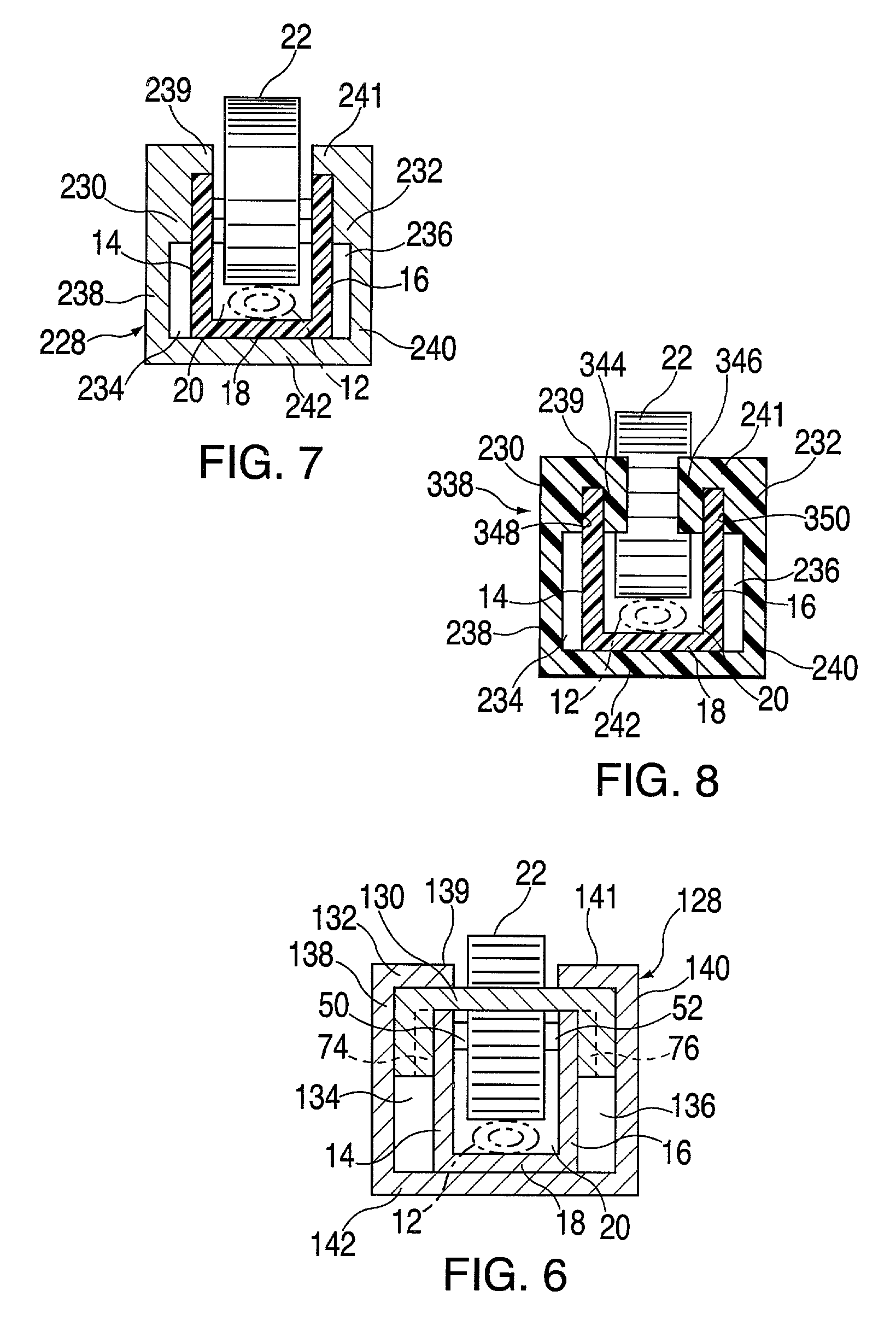
0031] In another embodiment of the present invention, the thickness of the side and bottom walls are increased at the shut-off or maximally restricted flow end of the device to minimize the distorting effect caused by the flexing and straining of the device when in use. Thereby, advantageously eliminated the need for a separate bracket, clip or bridge component made from a different type of material.
0032] In another embodiment of the present invention, the thickness of the side and bottom walls may be increased at discrete locations along the longitudinal channel of the device to further minimize the distorting effect caused by the flexing and straining of the device when in use.
0033] In a preferred embodiment of the present invention, the two side walls extend from the bottom wall at less than ninety degree angles such that distance between the free ends or edges of the side walls is smaller than the distance between the side walls where they meet the bottom wall. By angling the side walls towards each other, the increased thickness at the shut-off end of the device may be lessen in view of the additional counter effect caused by the flexing and straining of the device when in use. Thereby, advantageously resulting in the use of even less material and provides a more cost effective device.

Problems solved by technology

As suggested above, prior V-grooved or ramped roller clamps suffer from set-point drift attributable to shifting of the roller position.
The prior clamp structures are not believed to have taken into adequate consideration the direct effect of stress or strain as a critical contributing factor in degrading an accurate flow rate performance of the roller clamp.

Method used


Image

  • Flow regulator
  • Flow regulator
  • Flow regulator

Examples


Embodiment Construction

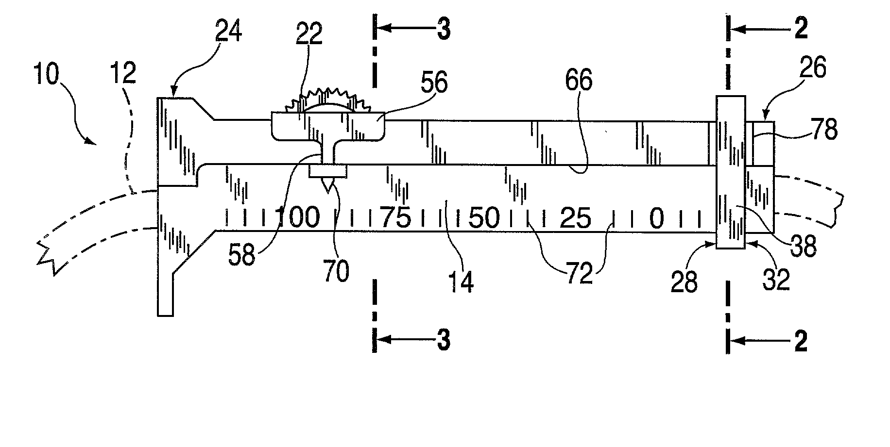
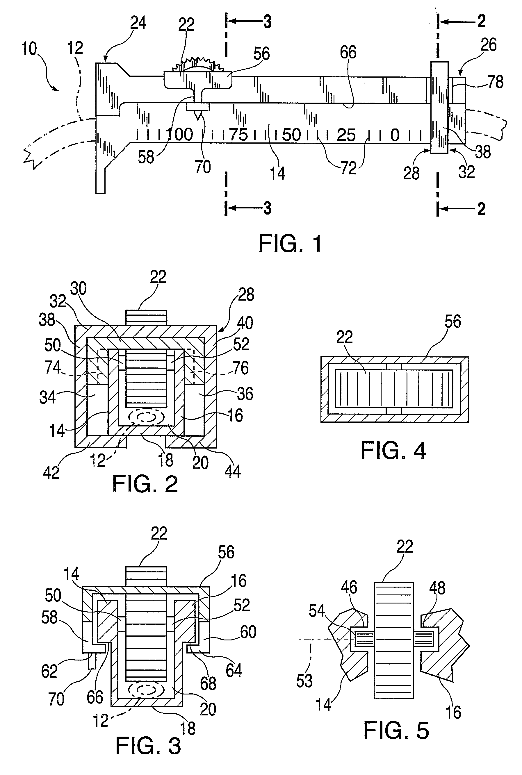
[0051] The drawings illustrate a flow regulator 10 intended for use with a compressible medical feed tube 12. The tube can deliver saline, blood, plasma, total parenteral fluids and other liquids to a patient, for example, to a blood vessel of the patient. Regulator 10 has a pair of side walls 14 and 16 which extend generally parallel to one another. A bottom wall 18 extends substantially the length of side walls 14 and 16 and connects the side walls to one another to define an elongate channel 20 for receiving tube 12. Channel 20 is generally open towards one side.

[0052] A roller 22 is rotatably and shiftably mounted to side walls 14 and 16. Roller 22 is partially disposed in channel 22 and partially extends through opening 21 for enabling the manual application of a torque to roller 22. Roller 22 is in frictional engagement with tube 12 for rolling along the tube in channel 20, under the manual application of torque, and compressing tube 12 against bottom wall 18. Bottom wall 18 i...


PUM


Abstract

A flow regulator has a pair of side walls extending generally parallel to one another, a bottom wall connecting the side walls to one another and defining an elongate channel for receiving a compressible tube, a roller rotatably and shiftably mounted to the side walls for rolling along the tube in the channel and compressing the tube against the bottom wall. The bottom wall is provided with a formation which varies from a first end of the channel towards an opposite, second end thereof, whereby compressive force applied to the tube via the roller is different at different longitudinal positions of the roller along the channel. A bracket or bow-shaped bridge is disposed about or between the side walls at one end of the channel. The bracket is in contact with outer surfaces of the side walls only in regions of the side walls spaced from the bottom wall. The bracket or bridge is advantageously made with less inherent stiffness than the assembly defining the elongate channel. In an alternative embodiment, the side walls are thicker at discrete positions along the side walls to eliminate the need for a bracket or bridge. In another alternative embodiment, the side walls extend from the bottom wall at less than ninety degree angles such that the distance between the free ends of the side walls are smaller than the distance between the side walls at the bottom wall.

Description

CROSS-REFERENCE TO RELATED APPLICATION[0001] This application claims the benefit of provisional application No. 60 / 332,992, filed Nov. 14, 2001. This is a continuation in part of application Ser. No. 09 / 624,664, filed Jul. 25, 2000, to be issued on Jan. 29, 2002 as U.S. Pat. No. 6,341,757, which was a continuation in part of provisional application No. 60 / 150,538 filed Aug. 25, 1999 and of application Ser. No. 09 / 319,456 filed as a U.S. national phase of international patent application No. PCT / US97 / 21617 which was filed Nov. 25, 1997 as a continuation in part of application Ser. No. 08 / 759,438 filed Dec. 5, 1996, now U.S. Pat. No. 5,718,409.FIELD OF THE INVENTION[0002] The invention relates to a flow regulator. More particularly, this invention relates to a flow regulator of the type which compresses a tube to vary a flow rate of a fluid passing through the tube. Even more particularly, this invention relates to a flow regulator of the roller type. The invention is useful in medica...

Claims


Application Information

Patent Timeline
Patent Type & Authority Applications(United States)
IPC IPC(8): A61M5/168A61M39/28
CPCA61M5/16881Y10T137/0346A61M39/28
Inventor STARCHEVICH, JOVANKA
Owner STARCHEVICH JOVANKA
Why Eureka
Try Eureka