Vacuum actuated brake pressure intensifier

a brake pressure intensifier and vacuum actuator technology, applied in the field of vehicle brakes, can solve the problems of driver inability to exert sufficient additional force on the brake pedal, inability to operate the entire hydraulic brake system, and substantial loss of brake pressure at normal pedal inputs

Inactive Publication Date: 2005-02-03
DELPHI TECH INC
View PDF15 Cites 7 Cited by
  • Summary
  • Abstract
  • Description
  • Claims
  • Application Information

AI Technical Summary

Benefits of technology

[0019] Our invention provides an improved power brake apparatus, meeting the requirements discussed above, through use of a hydraulic-pressure intensifier apparatus, that includes a hydraulic pressure intensifier controlled by a vacuum powered actuator. The hydraulic pressure intensifier defines a circuit for hydraulic fluid having an intensifier inlet for receiving hydraulic fluid from a master cylinder of the power brake apparatus at a master cylinder pressure, and an intensi

Problems solved by technology

A break in the fluid circuit anywhere rendered the entire hydraulic brake system inoperative.
A substantial loss of brake pressure at normal pedal inputs will be

Method used


Image

  • Vacuum actuated brake pressure intensifier
  • Vacuum actuated brake pressure intensifier
  • Vacuum actuated brake pressure intensifier

Examples


Embodiment Construction

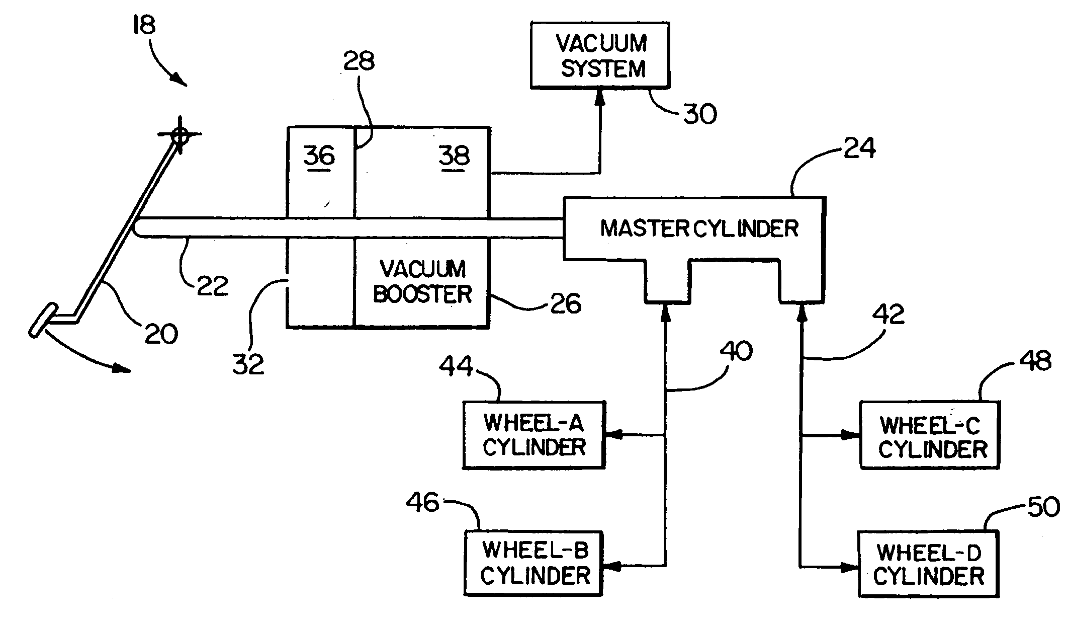
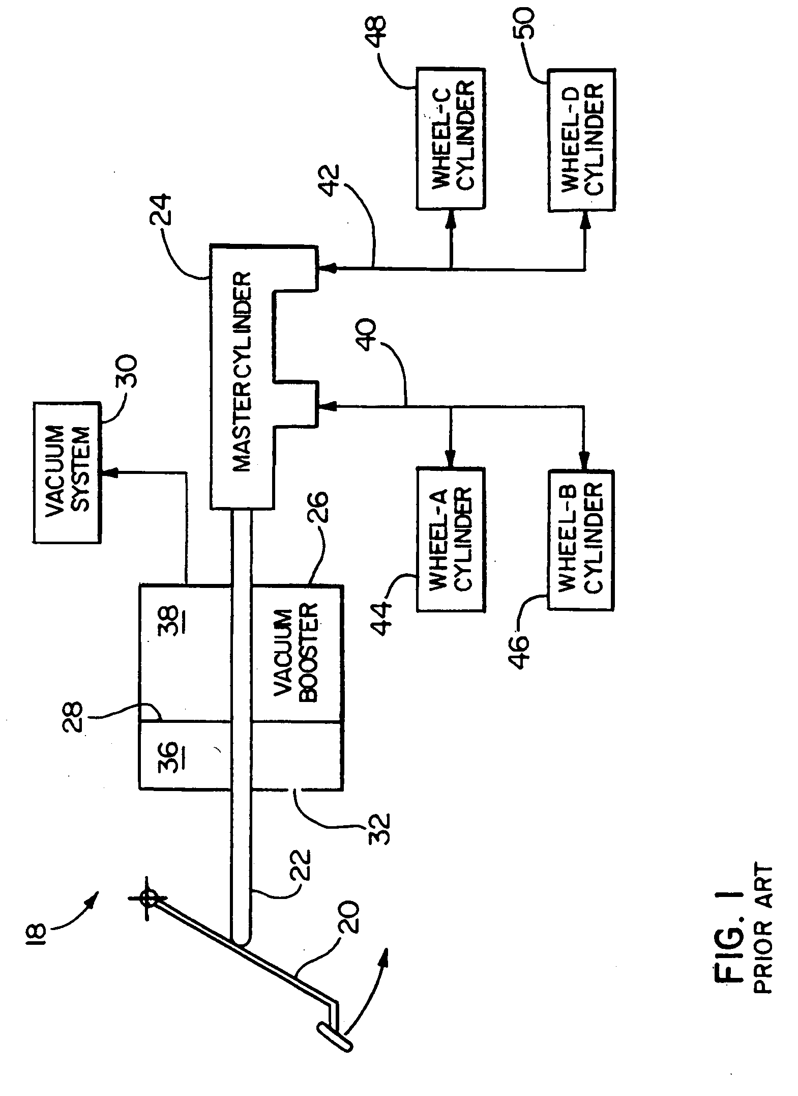
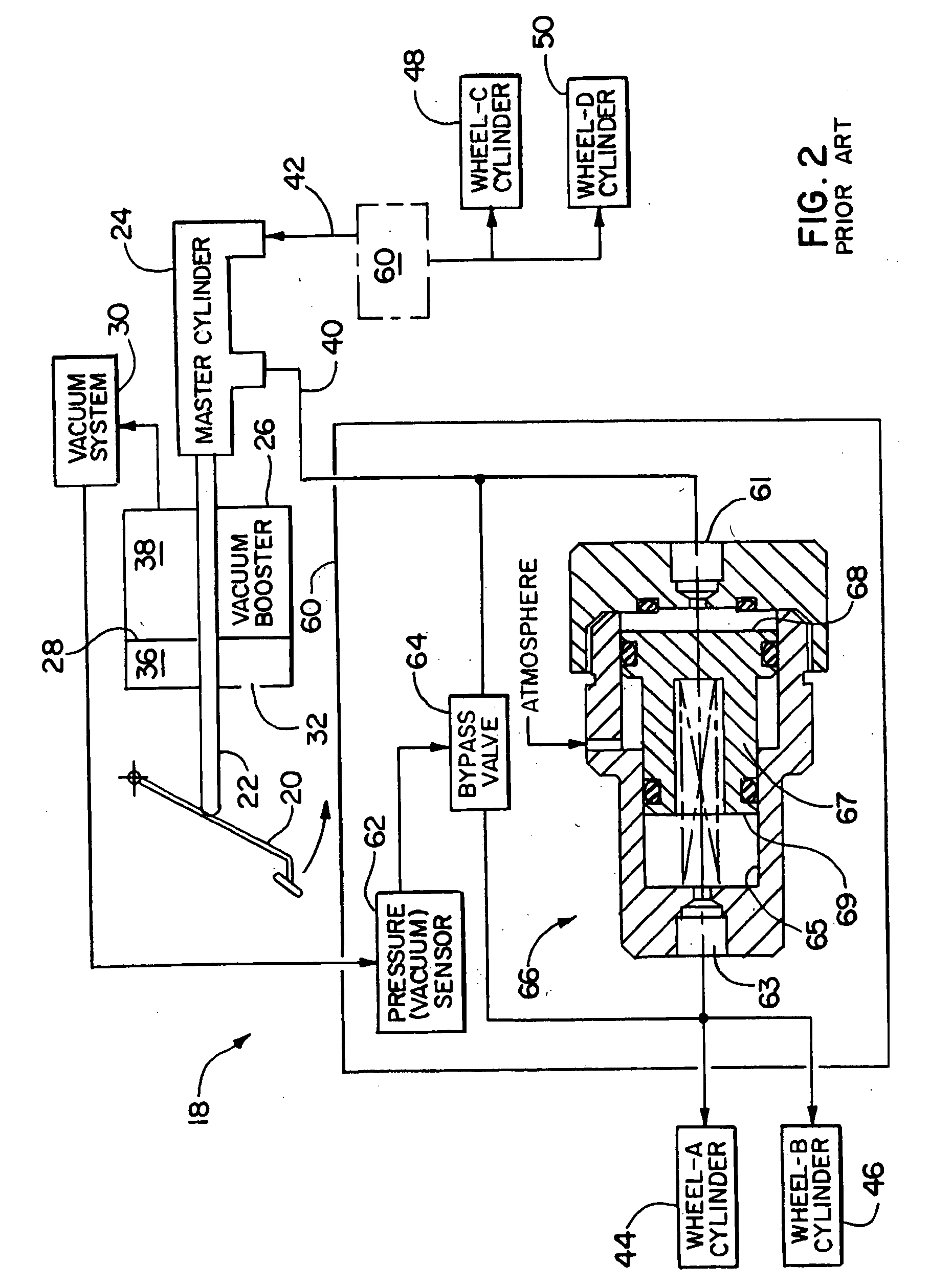
[0033]FIG. 3 shows a first exemplary form of a brake apparatus 70, including a vacuum powered hydraulic pressure intensifier apparatus 72, according to our invention. The embodiment depicted in FIG. 3 includes many of the same components that are used in the prior braking systems 18 discussed above with regard to FIGS. 1 and 2.

[0034] The exemplary embodiment of the brake apparatus 70 depicted in FIG. 3 includes four braking devices in the form of four wheel cylinders 44, 46, 48, 50. A master cylinder 24 supplies pressurized fluid at a master cylinder pressure brake lines 40, 42 to the braking devices 44, 46, 48, 50 in response to an input force applied to the master cylinder 24. The input force is applied to the master cylinder 24 by a push rod 22, connected to a brake pedal 20 and the diaphragm 28 of a vacuum booster 26. The vacuum booster 26 includes a front chamber 38 that is selectively connected to a vacuum source 30 by a control valve (not shown) within the booster 26 that is...


PUM


Abstract

A power brake apparatus includes a hydraulic pressure intensifier apparatus, having a hydraulic pressure intensifier controlled by a vacuum powered actuator. The hydraulic pressure intensifier defines a circuit for hydraulic fluid having an intensifier inlet for receiving hydraulic fluid from a master cylinder of the power brake apparatus at a master cylinder pressure, and an intensifier outlet for selectively delivering hydraulic pressure to a braking device at either the master cylinder pressure or at an intensified pressure higher than the master cylinder pressure. The vacuum powered actuator selectively controls the hydraulic pressure intensifier to deliver hydraulic fluid at the intensifier outlet at the master cylinder pressure when vacuum is available for providing power braking and at the intensified hydraulic pressure when vacuum is not available.

Description

TECHNICAL FIELD OF THE INVENTION [0001] This invention relates to vehicle brakes, and more particularly to a vehicle with a hydraulic brake apparatus including both a vacuum booster for providing power assisted braking, and a hydraulic brake booster that increases braking pressure when the vacuum booster is not operating. BACKGROUND OF THE INVENTION [0002] Since the mid 1930s, vehicles such as automobiles and light trucks have predominantly utilized hydraulic brake systems having a pedal operated master cylinder supplying pressurized hydraulic fluid to disk or drum braking devices at each wheel. [0003] Early hydraulic brake systems utilized a single hydraulic fluid circuit supplying pressurized fluid from the master cylinder to all four corners of the vehicle. A break in the fluid circuit anywhere rendered the entire hydraulic brake system inoperative. [0004] In order to prevent a total loss of hydraulic braking in the event of a failure of part of the system, failsafe hydraulic spl...

Claims


Application Information

Patent Timeline
IPC IPC(8): B60T13/48B60T13/52
CPCB60T13/52B60T13/48
Inventor FULKS, GARY C.HAERR, TIMOTHY A.POOLE, DOUGLAS E.
Owner DELPHI TECH INC
Why Eureka
Try Eureka