Drawer interlocking mechanism

Active Publication Date: 2005-02-03
NAN JUEN INT CO LTD
8 Cites 13 Cited by

AI-Extracted Technical Summary

Problems solved by technology

The required components are very complicated.
Its manufacturing cost is high, so it does not provide economical benefit.
Because the above-mentioned brake 13′ ha...

Benefits of technology

[0006] The inventor based on the need of a drawer interlocking mechanism improves the shortcomings of the above-mentioned drawer interlocking mechanism, so the axle cam design is simplified and components are easily assembled....

Abstract

An improved drawer interlocking mechanism mainly has a number of curved holes at equal angle along the peripheral of an axle hole in the base. There are flexible and moveable sticking tabs along the peripheral of an axle cam, which is allowed to freely rotate when it is installed into the axle hole of a base. After the axle cam rotates by an angle, the tab matches and locks into a curved hole for positioning. Two sets of brakes have symmetrical matching stoppers on two opposite sides, so the brakes can be placed into any slot of the base and a guide groove can be placed on the axle line corresponding to convex point. The groove surface has a stop to block the convex point, so the brake can slide and lead the direction with position limiting function. Thus, this can prevent the brake from dropping out of the slot.

Application Domain

Building locksWing fasteners

Technology Topic

PeripheralEngineering +3

Image

  • Drawer interlocking mechanism
  • Drawer interlocking mechanism
  • Drawer interlocking mechanism

Examples

  • Experimental program(1)

Example

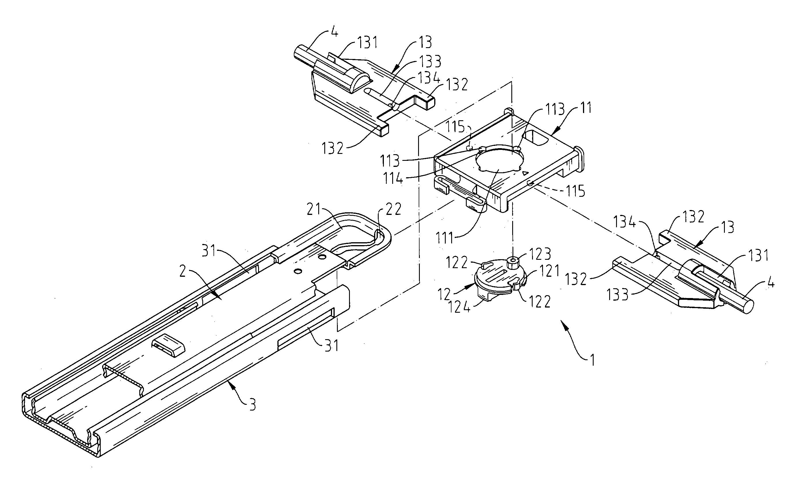
[0018] Please refer to FIG. 6 to FIG. 11. The invention provides an improved drawer interlocking mechanism 1 that mainly consists of a base 11, an axle cam 12 and two sets of brakes 13.
[0019] The base 11 is fixed to one end of the rail 3. There is a penetrating axle hole 111 in the base 11 and a slot 112 on the side of the base 11. At the corresponding position on the rail 3 to the slot 112, there is a corresponding slot 31 with same openness. Along the peripheral of the axle hole 111, there are several curved holes 113 every 90 degrees. At the bottom, there is a ladder surface 114. Besides, on the two sides of the slot 112, which are symmetrical to the central line of the axle hole 111, there are sticking convex points 115.
[0020] The axle cam 12 has a sticking gradient edge surface 121 on outer edge for the slot 112 to place into the above-mentioned axle hole 111 of the base 11 and match the ladder surface 114. Thus, one side of the axle cam 12 can be blocked by the rail 3. The other side can be blocked by the ladder surface 114 of base 11. The axle cam 12 is maintained in the axle hole 111 for free rotation without dropping out. On each edge of the groove at the two sides of the axle cam 12, there is a flexible and moveable tab 122 and a sticking top column 123 on the intercepting side of the tab 122, which allows the guide groove 22 on the flip cover 21 of the slider 2 to insert or take off and block the axle cam 12 that rotates by 90 degrees (refer to FIG. 8 and FIG. 9) Each 90-degree rotation makes the tab 122 lock into the curved hole 113 and provides a locking mechanism for the axle cam 12 in the axle hole 111 after rotating by 90 degrees (refer to Figure). In addition, there is a sticking block 124 at the bottom of the axle cam 12.
[0021] When the axle cam 12 is compared to the traditional axle cam 12′, it does not need to rely on the axle 121′, the spring 124′, the steel ball 125′ and the bottom convex 126′ to achieve 90-degree rotation, but needs only the locking mechanism comprising the sticking tab 122 on the peripheral and the curved hole 113 of the axle hole 111. This makes the locking mechanism design simplified. Besides, the traditional axle 121′ needs nails to stay on the front sticking plate of the rail 3′. The axle cam 12 in the present invention does not need nails for locking, but only needs the rail 3 for blocking and the axle hole 111 for locking on a gradient surface. The new design has very simple assembly.
[0022] The two sets of brakes 13 in pair are inserted into the slots 112 of the base 11. The external grooves 131 can incorporate the brake rod 4 with a sticking stopper 132 on each side. Thus, the connection formed is symmetrically placed into the slot 112 of the base 11 in any direction. Therefore, it does not need to identify the placement direction and simplify the assembly process. Further, the block 124 of the axle cam 12 is allowed to rotate in the space between the two stoppers 132. The brake 13 is inserted into a guide groove 133 along an axle line at the convex point 115 corresponding to the slot 112, so the convex point 115 can be placed in the groove for sliding guide. Besides, on the surface of where the guide groove 133 is introduced, there is a sticking stop 134 to block the convex point 115. Thus, it provides a position-limiting effect on the guide groove 133 that is moving outward and the guide groove 133 will be prevented from dropping out of the slot 112. Such drawer interlocking mechanism 1 can be assembled onto the slider 2 and the rail 3 at a time, so an integrated framework can be directly installed on the drawer. Also there is no need to assemble the two sets of brakes 13 separately. It offers a simplified and quick assembly method.
[0023] From the above description for the present invention in a practical application, as shown in FIG. 8, it is known that when the top column 123 for the axle cam 12 is driven by the guide groove 32 on the sticking plate of the rail 3, the axle cam 12 can rotate by 90 degrees and be positioned (refer to FIG. 9). The corresponding block 124 at the bottom of the axle cam 12 also rotates by 90 degrees and sets to a position. Now, the two sets of brakes 13 are pushed outward by the block 124, so the connected brake rod 4 can not move toward the two sets of brakes 13 (refer to FIG. 10). The brake rod 4 is blocked and the top and bottom drawers are locked. When the guide groove 32 for the rail 3 is inserted again to drive the rotation of the top column 123 of the axle cam 12. Thus, the block 124 at the bottom of the axle cam 12 rotates by 90 degrees and sets to a position. Immediately, the two ends of the two sets of brakes 13 have some space for the two brakes 13 to move inward against each other (refer to FIG. 11). The connected brake rod 4 also has shifting space that allows the top drawer or the bottom drawer unlocked.
[0024] As a result, the drawer interlocking mechanism in the present invention allows the rotation of the axle cam for positioning in a simplified design. Besides, the brake is modified to facilitate assembly. This greatly reduces manufacturing cost and assembly hours. It provides economic benefit and increases product competitiveness. The invention is a viable product with commercial value and progressiveness.

PUM

no PUM

Description & Claims & Application Information

We can also present the details of the Description, Claims and Application information to help users get a comprehensive understanding of the technical details of the patent, such as background art, summary of invention, brief description of drawings, description of embodiments, and other original content. On the other hand, users can also determine the specific scope of protection of the technology through the list of claims; as well as understand the changes in the life cycle of the technology with the presentation of the patent timeline. Login to view more.

Similar technology patents

Career Readiness and Planning System

InactiveUS20200219218A1increase abilityincrease competitiveness
Owner:I AM OKAH INC

TribonVitese secondary development method

PendingCN111625228Aincrease competitivenessprogramming language array convenience
Owner:上海拓境船舶科技有限公司

Composition for tire tread comprising resin alternative to process oil

ActiveUS20190144643A1improve gripping forceincrease competitiveness
Owner:KOLON IND INC

Method and system for disguised price bidding in online auctions

InactiveUS20080133398A1increase competitiveness
Owner:ARIBA INC

Classification and recommendation of technical efficacy words

  • increase competitiveness
  • easily assemble

Method and system for disguised price bidding in online auctions

InactiveUS20080133398A1increase competitiveness
Owner:ARIBA INC

Composition for tire tread comprising resin alternative to process oil

ActiveUS20190144643A1improve gripping forceincrease competitiveness
Owner:KOLON IND INC

TribonVitese secondary development method

PendingCN111625228Aincrease competitivenessprogramming language array convenience
Owner:上海拓境船舶科技有限公司

Career Readiness and Planning System

InactiveUS20200219218A1increase abilityincrease competitiveness
Owner:I AM OKAH INC

Adaptor for reducing EMI

InactiveUS20050111796A1easily assemblereduce aperture
Owner:MOLEX INC

Capacitive Sensor and Method and Apparatus for Controlling a Pump Using Same

ActiveUS20080229819A1easily assemblereduce cost associate with assembly and/or material cost
Owner:WAYNESCOTT FETZER

Quick pipe connector

Owner:YANG RICHARD

Pouch-Equipped Intragastric Balloon

InactiveUS20080243166A1easily assemble
Owner:CIE EURO D'ETUDES & DE RECH DE DISPOSITIFS POUR L'IMPLANTATION PAR LAPAROSCOPIE

Component carrier

InactiveUS6995983B1less susceptibleeasily assemble
Owner:X2Y ATTENUATORS L L C
Why Eureka
Try Eureka