Textile dip dyeing equipment

An equipment and textile technology, applied in the field of textile impregnation and dyeing equipment, can solve the problems of affecting processing quality, producing mucus, difficult to color, etc., to achieve the effect of improving processing quality, prolonging service life and reducing centrifugal force

Inactive Publication Date: 2021-02-26
邓苗苗
View PDF1 Cites 0 Cited by
  • Summary
  • Abstract
  • Description
  • Claims
  • Application Information

AI Technical Summary

Problems solved by technology

[0005] Aiming at the deficiencies of the prior art, the present invention provides a kind of textile exhaust dyeing equipment, which can solve the problem that the textiles are completely immersed in the dyeing solution during the use of the existing exhaust dyeing equipment, but the fibers are close to each other, it is difficult to color the inside, and the exhaust dyeing consumes a lot of time. It takes a long time and wastes time. The surface of the textile is easy to produce mucus due to soaking, which will damage the quality of the textile and affect the processing quality.

Method used


Image

  • Textile dip dyeing equipment
  • Textile dip dyeing equipment
  • Textile dip dyeing equipment

Examples


Embodiment

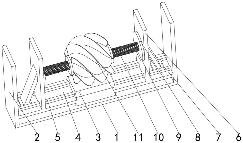
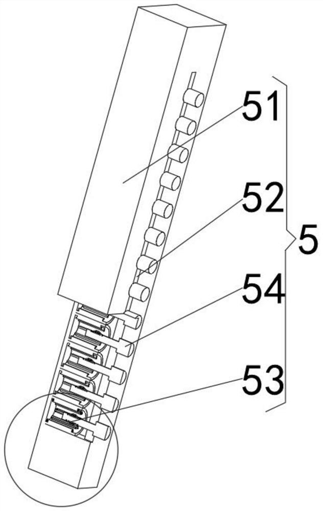
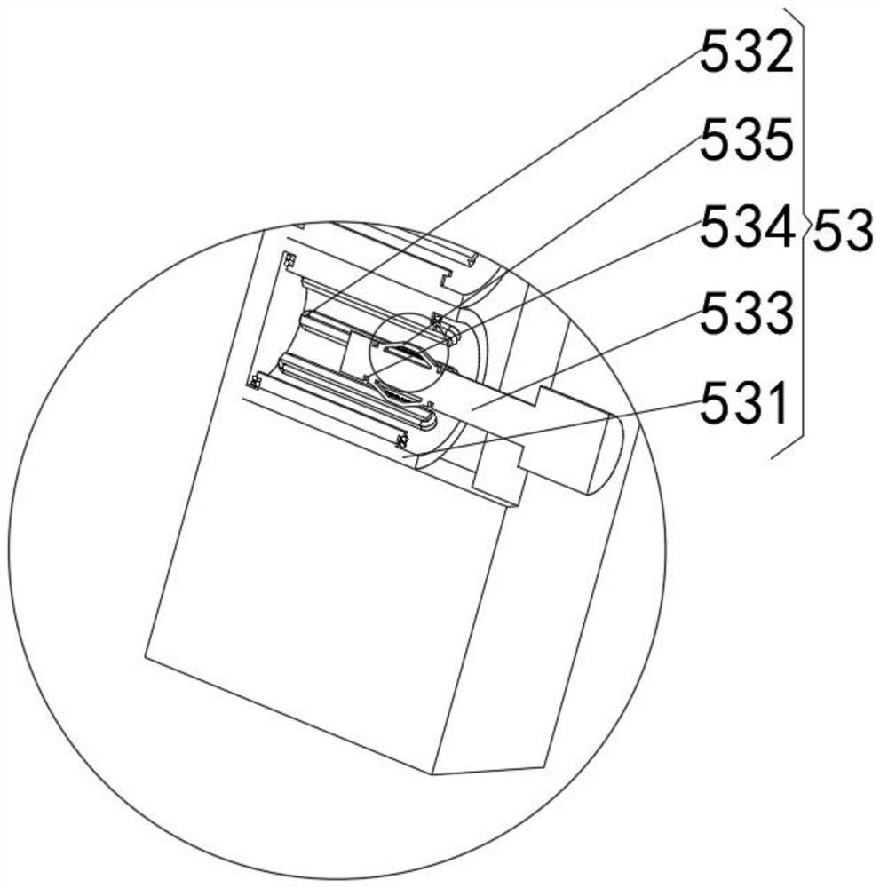
[0039] see Figure 1-7 , the present invention provides a technical solution: a textile dip-dyeing equipment, including a base plate 1, the symmetrical positions on both sides of the top of the base plate 1 are fixedly connected with protective baffles 2, and the middle position of the top of the base plate 1 is fixedly connected with a magnetic force electromagnet 3 The middle position of the outer wall on both sides of the magnetic force electromagnet 3 is fixedly connected with the track plate 4, the top front and back of the track plate 4 are fixedly connected with the power generation track 5, the top of the outer surface of the power generation track 5 is slidingly connected with the force plate 6, and the force plate 6 The friction bracket 7 is fixedly connected to the middle position of the sides far away from each other, the mounting plate 8 is fixedly connected to the side where the force applying plates 6 are close to each other, and the modulation rod 9 is fixedly c...


PUM


Abstract

The invention discloses textile dip dyeing equipment, and relates to the technical field of textile. The textile dip dyeing equipment comprises a base plate, protective baffles are fixedly connected to the symmetrical positions of the two sides of the top of the base plate, a magnetic electromagnet is fixedly connected to the middle position of the top of the base plate, and rail plates are fixedly connected to the middle positions of the outer walls of the two sides of the magnetic electromagnet. Power generation rails are fixedly connected to the front faces and the back faces of the tops ofthe rail plates, friction supports are fixedly connected to the middle positions of the sides, away from each other, of force application plates, and modulation rods are fixedly connected to the middle positions of the sides, away from the friction supports, of mounting discs. A traction rope is fixedly connected to the side, away from the friction supports, of the mounting discs, and a dip dyeing box is fixedly connected to the end, away from the mounting discs, of the traction rope. Power is applied through airflow flowing, textiles and dip dyeing liquid move mutually, the dip dyeing progress is promoted, the dip dyeing time is shortened, and the quality of the textiles is protected.

Description

technical field [0001] The invention relates to the technical field of textiles, in particular to a textile dip-dyeing equipment. Background technique [0002] Textile is a general term derived from spinning and weaving, but with the continuous development and improvement of the textile knowledge system and subject system, especially after the emergence of technologies such as non-woven textile materials and three-dimensional composite weaving, the current textile is not only a traditional handicraft Spinning and weaving also include non-woven fabric technology, modern three-dimensional weaving technology, modern electrostatic nano-netting technology and other textiles for clothing, industrial use and decoration, as well as clothing, airbags and curtains and carpets in daily life. textile. The exhaust dyeing step is a very important step in the textile processing process. [0003] According to Chinese patent CN109898252A, there are support seats on both sides of the upper ...

Claims


Application Information

Patent Timeline
Patent Type & Authority Applications(China)
IPC IPC(8): D06B3/20D06B3/34D06B23/04D06B23/18D06B23/20
CPCD06B3/20D06B3/208D06B3/34D06B23/04D06B23/18D06B23/20
Inventor 邓苗苗
Owner 邓苗苗
Why Eureka
Try Eureka