
Optical alignment method and apparatus

a technology of optical alignment and equipment, applied in the field of multi-axis machine tool set-up and calibration, can solve the problems of poor quality parts, considerable waste, and unusable traditional laser interferometers, and achieve the effects of reducing the chance of errors, improving accuracy and repeatability, and shortening the time needed for set-up

Inactive Publication Date: 2005-02-03
EXCEL PRECISION
View PDF1 Cites 19 Cited by
  • Summary
  • Abstract
  • Description
  • Claims
  • Application Information

AI Technical Summary

Benefits of technology

[0015] An advantage of the present invention is that it significantly shortens the time needed for set-up and calibration of a multi-axis machine tool, such as computer numerical control (CNC) and coordinate measuring machine (CMM) systems.
[0016] Another advantage of the invention is that it does not require moving a laser head during set-up and calibration of a multi-axis machine tool, thus reducing opportunity for errors and improving accuracy and repeatability.
[0017] Another advantage of the invention is that it can reduce or eliminate the need for a calibration specialist set-up and calibration of a multi-axis machine tools.
[0018] And another advantage of the invention is that it can work with single and multi-beam laser heads, thus providing improvements in set-up and calibration times as well as the providing the additional accuracy and measurement parameter capabilities that the latter type of laser head provides.
[0019] These and other objects and advantages of the present invention will become clear to those skilled in the art in view of the description of the best presently known mode of carrying out the invention and the industrial applicability of the preferred embodiment as described herein and as illustrated in the several figures of the drawings.

Problems solved by technology

The traditional laser interferometer, however, is not a very user-friendly device.
The users of CNC / CMM systems consequentially often have to bear the cost of a calibration specialist, as well as the loss of revenue, staff re-tasking, etc., while the CNC / CMM system is unavailable.
The net result of all of this is often the production of poor quality parts and considerable waste.
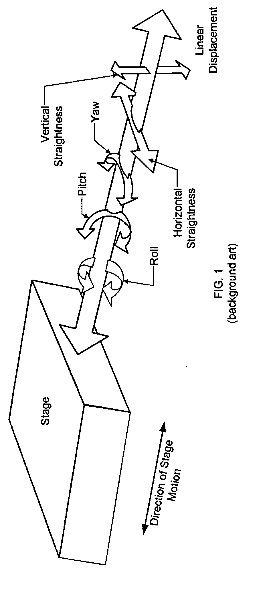
And since positional accuracy is lost in each such change, a new reference has to be established whenever the laser head is moved.
However, like traditional systems, the 1100B system can only measure one axis at a time, and the laser head used therefore needs to be moved and oriented and the alignment process started over for each axis.

Method used


Image

  • Optical alignment method and apparatus
  • Optical alignment method and apparatus
  • Optical alignment method and apparatus

Examples


Embodiment Construction

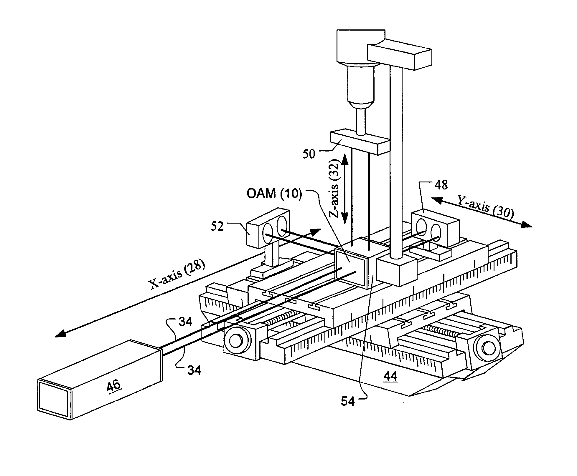
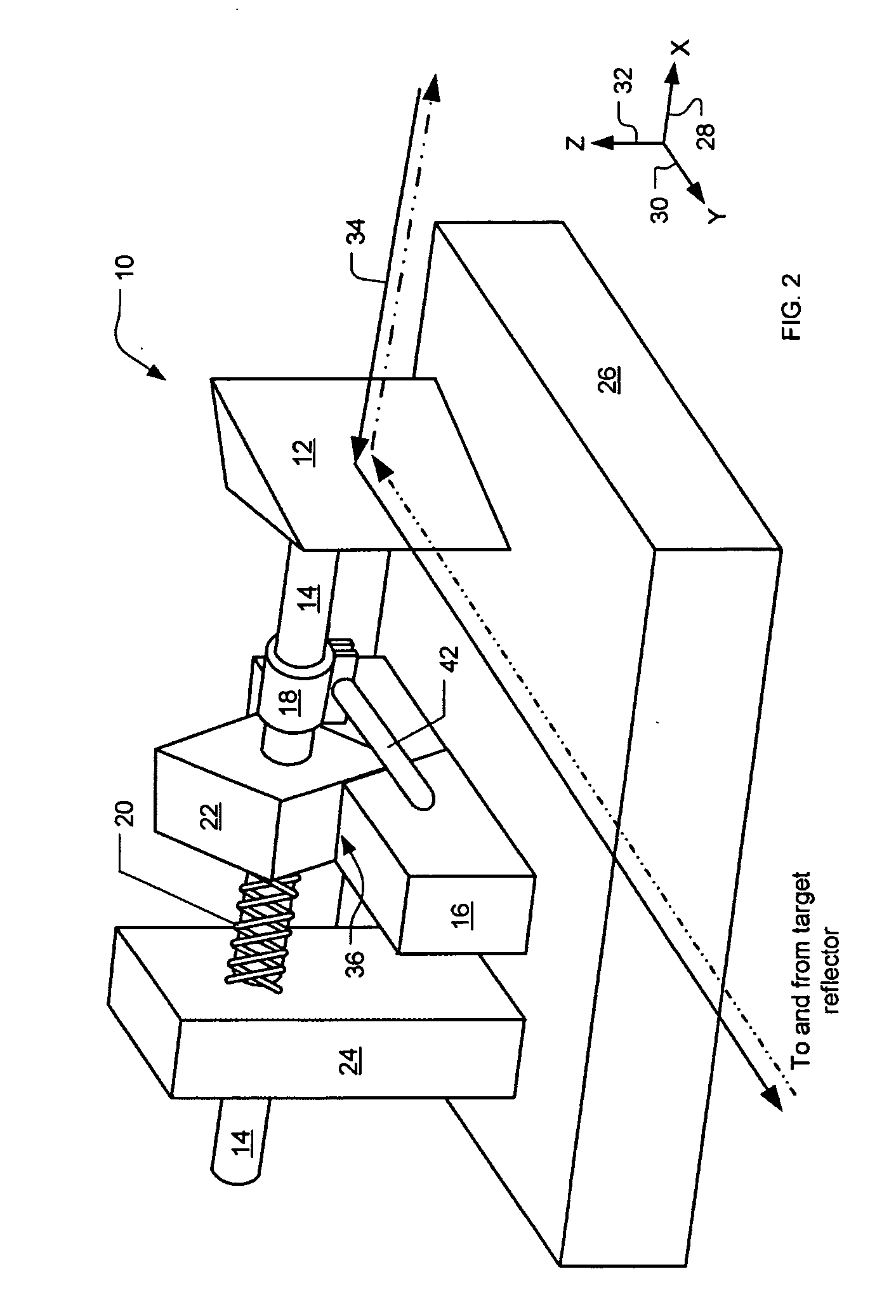
[0031] A preferred embodiments of the present invention are methods and apparatus for optical alignment to calibrate multi-axis machine tools, particularly including computer numerical control (CNC) and coordinate measuring machine (CMM) systems. As illustrated in the various drawings herein, and particularly in the views of FIG. 2-10, exemplary embodiments of the invention are depicted by the general reference character 10.

[0032] The inventive method and apparatus permit a single set-up of a laser head, and measurement of the axes of a multi-axis machine tool such as a CNC or CMM system. This approach is generally applicable to any type of laser head used for such calibration, to reduce the overall set up time as well as to preserve accuracy, because the laser head does not have to be repeatedly repositioned.

[0033]FIG. 2 is a conceptual side perspective view showing an example of a basic embodiment of an “optical alignment module” (OAM 10) in accord with the present invention. Th...


PUM


Abstract

A method establishing a reference point for a machine tool with X-, Y-, and Z-stages. A YZ-plane is established by reflecting a light beam off an X-stage reflector to sense at a detector. The X-stage is moved while repositioning the head and reflector and maintaining sensing. An optical alignment module (OAM) is mounted optically perpendicular to the beam, with a bending mirror centered at the Z-axis. The Z-axis is established bending mirror deflecting the beam to the Z-axis, reflecting it off of a Z-stage reflector so it is sensed, and moving the Z-stage while repositioning the OAM relative to the X- and Y-axes to maintain sensing. An XY-plane is established by bending mirror deflecting the beam to the Y-axis, reflecting it off of a Y-stage reflector so it is sensed, and moving the Y-stage while repositioning the Y-reflector relative to the X- and Z-axes to maintain sensing.

Description

[0001] This application claims the benefit of U.S. Provisional Application No. 60 / 481,021, filed Jun. 25, 2003.TECHNICAL FIELD [0002] The present invention relates generally to set-up and calibrate multi-axis machine tools, and particularly computer numerical control (CNC) and coordinate measuring machine (CMM) systems. BACKGROUND ART [0003] The laser interferometer is an important device for calibrating multi-axis machine tools, particularly including computer numerical control (CNC) and coordinate measuring machine (CMM) systems. In fact, the laser interferometer is currently the only device known to the inventor that is used for calibrating the latter types of equipment. With the rising demand for precise, machined parts in industry, the use of machine tooling in general, and CNC and CMM tools in particular, is increasing and calibrating these systems is becoming more and more important. [0004] The traditional laser interferometer, however, is not a very user-friendly device. It ...

Claims


Application Information

Patent Timeline
Patent Type & Authority Applications(United States)
IPC IPC(8): G01B11/03G01B11/14G01B21/04
CPCG01B21/042
Inventor TSAI, JOHN C.
Owner EXCEL PRECISION
Learn More