Near-field optical probe for reproducing information on a recording medium using near-field light

a near-field light and optical probe technology, applied in nanoinformatics, instruments, record information storage, etc., can solve the problems of difficult near-field optical, inability to achieve high resolution observation, and density of information recording that cannot be achieved by conventional optical microscopes

Inactive Publication Date: 2005-02-03
SEIKO INSTR INC
View PDF8 Cites 2 Cited by
  • Summary
  • Abstract
  • Description
  • Claims
  • Application Information

AI Technical Summary

Benefits of technology

[0026] According to this invention, the first microscopic aperture for producing near field light is formed by locally coating the shade film. The phase shifter is formed in a manner closing the first microscopic aperture, which is transparent for a wavelength of laser light (illumination light) to be introduced to the through-hole to cause a 180-degree shift of phase in the laser light. The second microscopic aperture is provided in the

Problems solved by technology

However, the information recording density has reached a limitation because of a presence of a diffraction limit of laser light.
Thus, high resolution of observation is made feasible that could not be achieved by the conventional optical microscopes.
However, where the recording medium is increased in recording density by arranging data marks as information units in a close relationship, when conducting reproducing with the recording medium there encounters difficulty for the near-field optical probe used in the convent

Method used


Image

  • Near-field optical probe for reproducing information on a recording medium using near-field light
  • Near-field optical probe for reproducing information on a recording medium using near-field light
  • Near-field optical probe for reproducing information on a recording medium using near-field light

Examples


embodiment 1

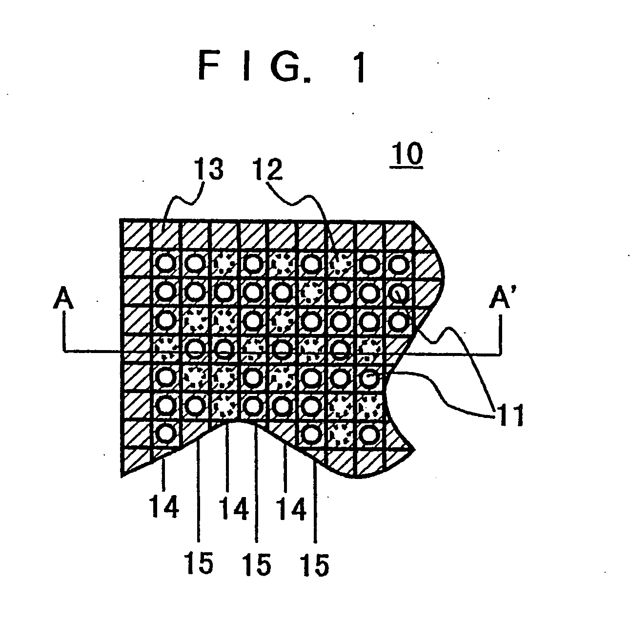
[0041] Referring to FIG. 1, there is illustrated one part of a recording medium according to Embodiment 1 of the present invention. A recording medium 10 in the figure includes a substrate having a sufficient transmittance of light to produce near-field light, on which is formed a phase shifter arrangement layer, hereinafter referred to. Furthermore, a data mark arrangement layer is formed on the phase shifter arrangement layer. Herein, the data mark arrangement layer is a region to be formed with a data mark.

[0042] In FIG. 1, the recording medium 10 has a data mark arrangement layer to be formed with data marks 11 serving as the light transmittance regions to produce comparatively intense near-field light, for example. The proper arrangement of data marks 11 makes possible to achieve information recording. Note that in the figure the circle 12 depicted by a dotted line represents a position that a data mark is possible to provide therein. It is assumed herein that the data mark 11...

embodiment 2

[0053] Explanations will be now made on a recording medium according to Embodiment 2. FIG. 3 shows one part of the recording medium of Embodiment 2. The recording medium 20 of FIG. 3 is different from the recording medium 10 according to Embodiment 1 only in that no shade film is coated over a surface of the recording medium. Accordingly, the recording medium 20 of FIG. 3 is structured by a phase shifter arrangement layer formed on a base member having a sufficient transmittance for producing near-field light, and a data mark arrangement layer formed on the phase shifter arrangement layer.

[0054] Here, the phase shifter arrangement layer is formed alternately with a phase shifter regions 24 and transmission regions 25 similarly to Embodiment 1 while the data mark arrangement layer is a region where data marks 21 are to be formed. Note that circles 22 shown by dotted lines in the figure represent positions that data marks are possible to provide.

[0055] Meanwhile, in FIG. 1 the shade...

embodiment 3

[0063] Explanations will now be made on a recording medium according to Embodiment 2. FIG. 5 shows one part of the recording medium of Embodiment 3. The recording medium 30 of FIG. 5 has a phase shifter 33 coated on a base member having a sufficient transmittance for producing near-field light, and data marks 31 provided in areas not coated with the phase shifter 33 thus storing information. Note that circles 32 shown by dotted lines represent positions that data marks are possible to provide. Here, the phase shifter 33 has a transmittance of approximately 2-20% for a wavelength of an oozing portion of the incident light illuminated at the backside of the recording medium 30 under a condition of total reflection. The phase shifter is also formed of a translucent material having a phase difference of 180 degrees with respect to the base member 36 of the recording medium 30 (particularly, the translucent phase shifter is referred to as a half-tone type phase shifter), e.g. an applied ...


PUM


Abstract

A near-field optical probe has a planar substrate formed with a through-hole and a phase shifter layer translucent to light having a wavelength of illumination light used to illuminate the substrate for producing near-field light. The phase shifter layer is effective to cause a shift of phase in the illumination light by 180 degrees and is provided on the substrate so as to cover one opening of the through-hole to form a microscopic aperture for producing near-field light.

Description

BACKGROUND OF THE INVENTION [0001] This invention relates to a recording medium reproducible by utilizing near-field light and a near-field optical probe for reproducing information recorded on such a recording medium and, more particularly to-a recording medium and near-field optical probe that enhances reproducing resolution for information recorded with density. [0002] In recent years, remarkable development has been made in optical reproducing apparatuses (DVD players, etc.) for reproducing information on recording media by illuminating laser light. However, the information recording density has reached a limitation because of a presence of a diffraction limit of laser light. In an attempt to break through such diffraction limit, a proposal has been made on a near-field light reproducing apparatus using an optical head provided with a microscopic aperture having a diameter of less than a wavelength of laser light to be utilized in reproducing so that near-field light (including ...

Claims


Application Information

Patent Timeline
IPC IPC(8): G01B21/30G01N37/00G01Q60/18G01Q80/00G01Q90/00G11B7/005G11B7/007G11B7/12G11B7/24G11B7/241
CPCB82Y10/00G11B7/24G11B7/12G11B7/005
Inventor OUMI, MANABUMITSUOKA, YASUYUKICHIBA, NORIOKASAMA, NOBUYUKIKATO, KENJINIWA, TAKASHI
Owner SEIKO INSTR INC
Why Eureka
Try Eureka